#retaining-wall#is-456#cantilever-wall#earth-pressure#rcc-design#geotechnical
Retaining Wall Design (IS 456) — Cantilever Example
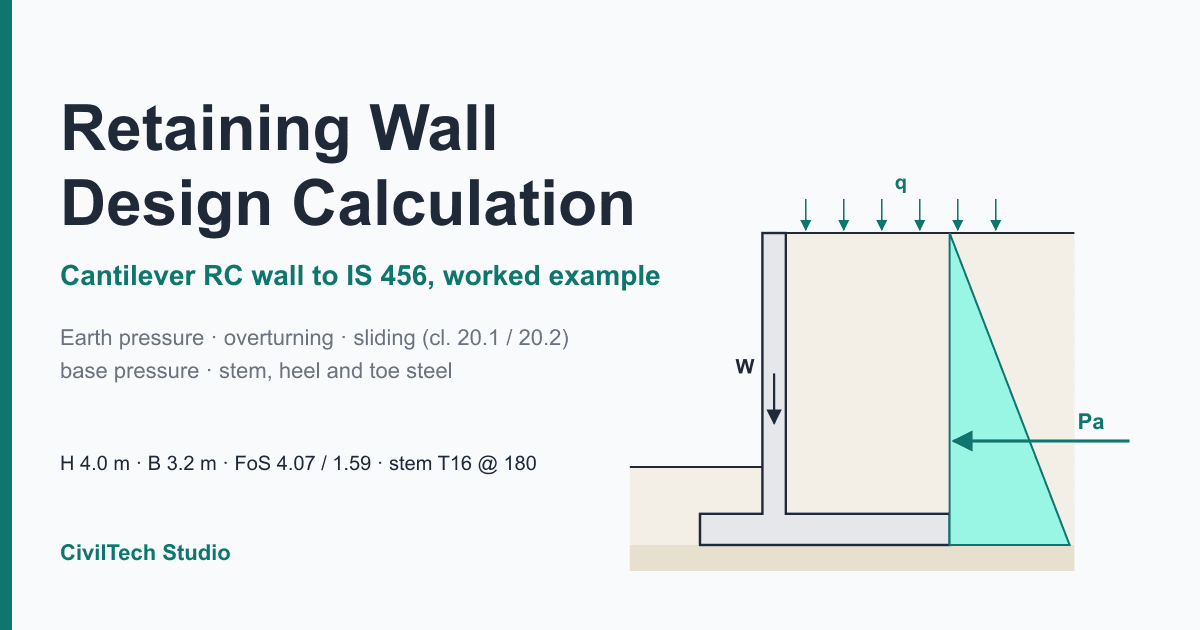
A complete retaining wall design calculation for a 4.0 m cantilever RC wall to IS 456: earth pressure, overturning, sliding (cl. 20.1/20.2), base pressure, stem, heel and toe steel, with every number checked by hand and by the CivilTech Studio engine.
Updated 4 Nov 202621 min read
 Try it free: open this worked example in Retaining Wall DesignerOpen →
On this page
- What governs a cantilever retaining wall design
- Proportioning rules of thumb
- Step-by-step retaining wall design procedure
- Worked example: 4.0 m cantilever retaining wall to IS 456
- IS 456 clause reference for retaining wall design
- IS 456 vs ACI 318 vs Eurocode: factors of safety or partial factors
- Rankine vs Coulomb vs Mononobe-Okabe earth pressure
- Common mistakes in retaining wall calculations
- How CivilTech Studio does this
- FAQ
Retaining Wall Design Calculation to IS 456: Cantilever Wall Worked Example
By the CivilTech Studio Engineering Team
A retaining wall design calculation for a cantilever RC wall has two halves. First, the wall must stay put as a rigid block: it must not overturn about the toe, slide on its base, or press the soil harder than the soil can take. Second, each part (stem, heel and toe) is a cantilever slab that needs enough depth and steel for its own bending and shear. Stability usually fixes the base width. Strength fixes the thicknesses and the bars. Under IS 456, overturning and sliding are checked to cl. 20.1 and 20.2, along with the higher practice factors of safety of 2.0 and 1.5. The members are designed to limit state (Annex G for flexure, Table 19 for shear). This guide works through a 4.0 m wall by hand and checks every number against the CivilTech Studio retaining wall design calculator.
What governs a cantilever retaining wall design
Think of the wall as a block of concrete with a block of soil standing on its heel. The backfill pushes horizontally. The weight of the concrete and the heel soil holds the wall back. Four things can go wrong:
- Overturning about the toe. This is rarely critical once the heel is long enough to resist sliding.
- Sliding along the base. With dry, cohesionless soil and no shear key, this usually sets the base width.
- Bearing. The peak toe pressure must stay below the allowable bearing pressure, and the resultant should stay in the middle third (e ≤ B/6) so the heel does not lift off.
- Member strength. The stem root, the heel at the back face of the stem and the toe at the front face each carry a cantilever moment. The stem usually needs the most steel.
Deep-seated slip of the soil under and around the wall (global stability) and serviceability (crack width, stem deflection) complete the list.
Proportioning rules of thumb
Start from textbook proportions, then let the checks correct them:
| Dimension | Typical starting value | This example (H = 4.0 m) |
|---|---|---|
| Base width B | 0.5H to 0.7H (more for low μ or with surcharge) | 3.2 m (0.8H) |
| Toe length | about B/4 to B/3 | 0.8 m |
| Base thickness | H/10 to H/12, at least 300 mm | 400 mm |
| Stem thickness at base | H/10 to H/12 | 300 mm |
| Stem thickness at top | 150 to 200 mm minimum (or keep it prismatic) | 300 mm (prismatic) |
Our base ends up wider than the usual rule. With μ = 0.5, a live surcharge and no passive resistance or shear key, sliding needs a long heel. The worked example shows exactly how long.
Step-by-step retaining wall design procedure
Step 1: Define H correctly
H is the total height from the underside of the base slab to the top of the retained ground at the back of the stem. It is not the visible height above the front ground. The stem height is hs = H − base thickness. Earth thrust grows with H² and its overturning moment with H³. If you use the exposed height instead, everything comes out too small.
Step 2: Earth pressure coefficient
For a vertical back, level backfill and no wall friction (Rankine):
Ka = (1 − sin φ) / (1 + sin φ) = tan²(45° − φ/2)
Kp = (1 + sin φ) / (1 − sin φ)
Step 3: Forces and lever arms about the toe
Earth thrust      Pa = 0.5 × Ka × γ × H²        acting at H/3 above the base underside
Surcharge thrust  Ps = Ka × q × H               acting at H/2
Weights           W = volume × unit weight      acting at each centroid
Earth pressure acts on a vertical "virtual back" through the heel edge. The soil above the heel therefore counts as part of the wall's weight.
Step 4: Overturning
FoS_OT = ΣM_resisting / ΣM_overturning (about the toe)
Only permanent weights resist. A live surcharge on the heel pushes the wall but must not hold it back, because it may not be there when the thrust acts. Soil over the toe may be dug away for services, so it is not relied on either.
Step 5: Sliding
FoS_SL = (μ × ΣV + passive resistance) / ΣH
Passive resistance in front of the toe is real but needs large movement to develop. Common practice is to halve it, ignore the top 0.5 m, or leave it out entirely unless a shear key is provided.
Step 6: Base pressure
x̄ = (ΣM_R − ΣM_O) / ΣV          (resultant position from the toe)
e = B/2 − x̄
q_max, q_min = (ΣV / B) × (1 ± 6e / B)      valid while e ≤ B/6
Step 7: Member design
Under IS 456 Table 18 load factors, design the stem as a cantilever from the top of the base. The heel is checked at the back face of the stem, and the toe at the front face. Steel comes from Annex G:
Ast = 0.5 × (fck / fy) × [1 − √(1 − 4.6 Mu / (fck b d²))] × b × d
Shear is checked as τv = Vu / (b d) against k × τc from Table 19. The stem shear is taken at d above the base.
Step 8: Detailing and serviceability
Check minimum steel (0.12 % of bD for HYSD bars, cl. 26.5.2.1), bar spacing (≤ 3d or 300 mm, cl. 26.3.3), the development length of the stem bars into the base, crack width (Annex F) and stem deflection (cl. 23.2).
Worked example: 4.0 m cantilever retaining wall to IS 456
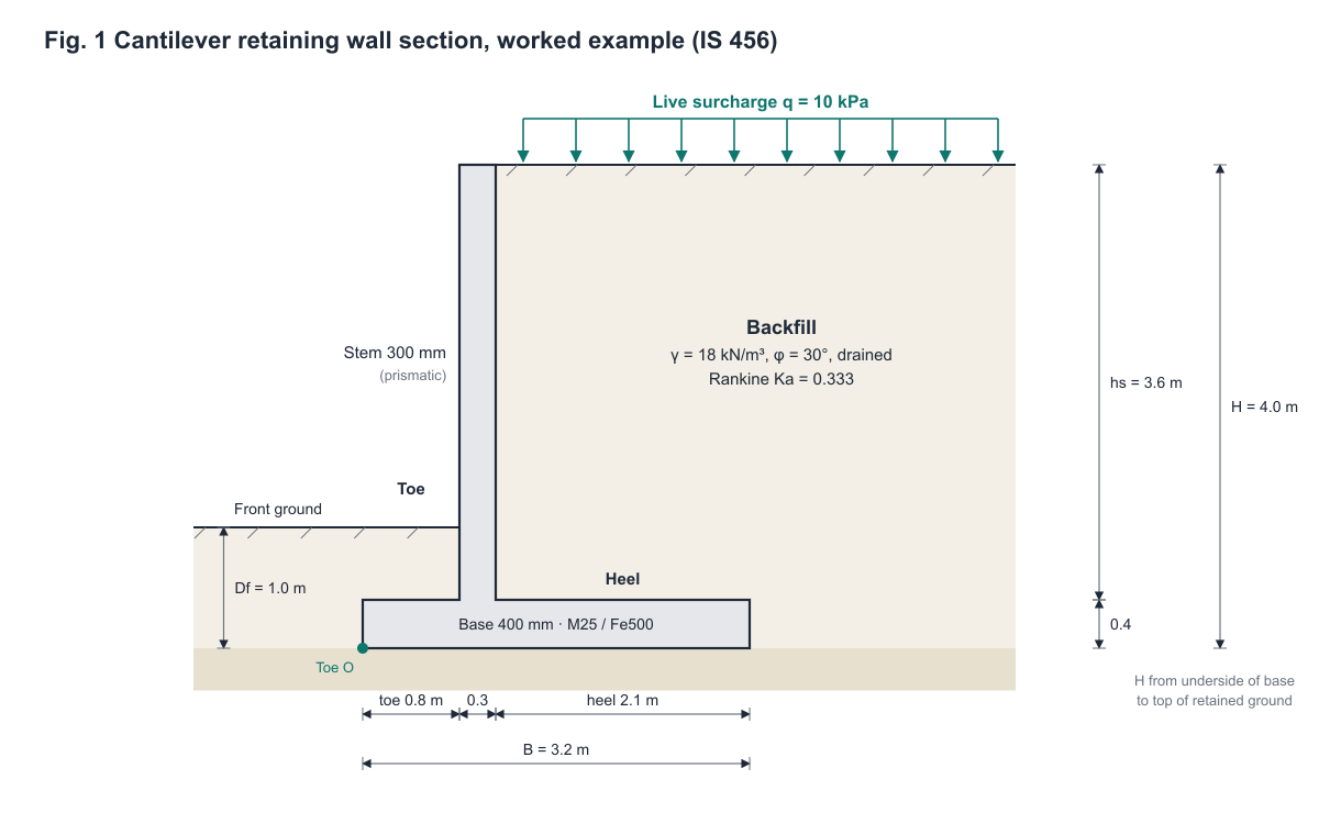
Inputs
| Parameter | Value |
|---|---|
| Total height H (underside of base to top of fill) | 4.0 m |
| Stem | 300 mm, prismatic; stem height hs = 3.6 m |
| Base | 400 mm thick, toe 0.8 m, heel 2.1 m, B = 3.2 m |
| Backfill | γ = 18 kN/m³, φ = 30°, level, dry (drained) |
| Live surcharge q | 10 kPa |
| Foundation | μ = 0.5, allowable bearing (SBC) 180 kPa, front ground 1.0 m above the base underside |
| Materials | M25 concrete (γc = 25 kN/m³), Fe500 steel, 50 mm cover |
| Earth pressure | Rankine; passive resistance not counted |
Earth pressure and driving forces
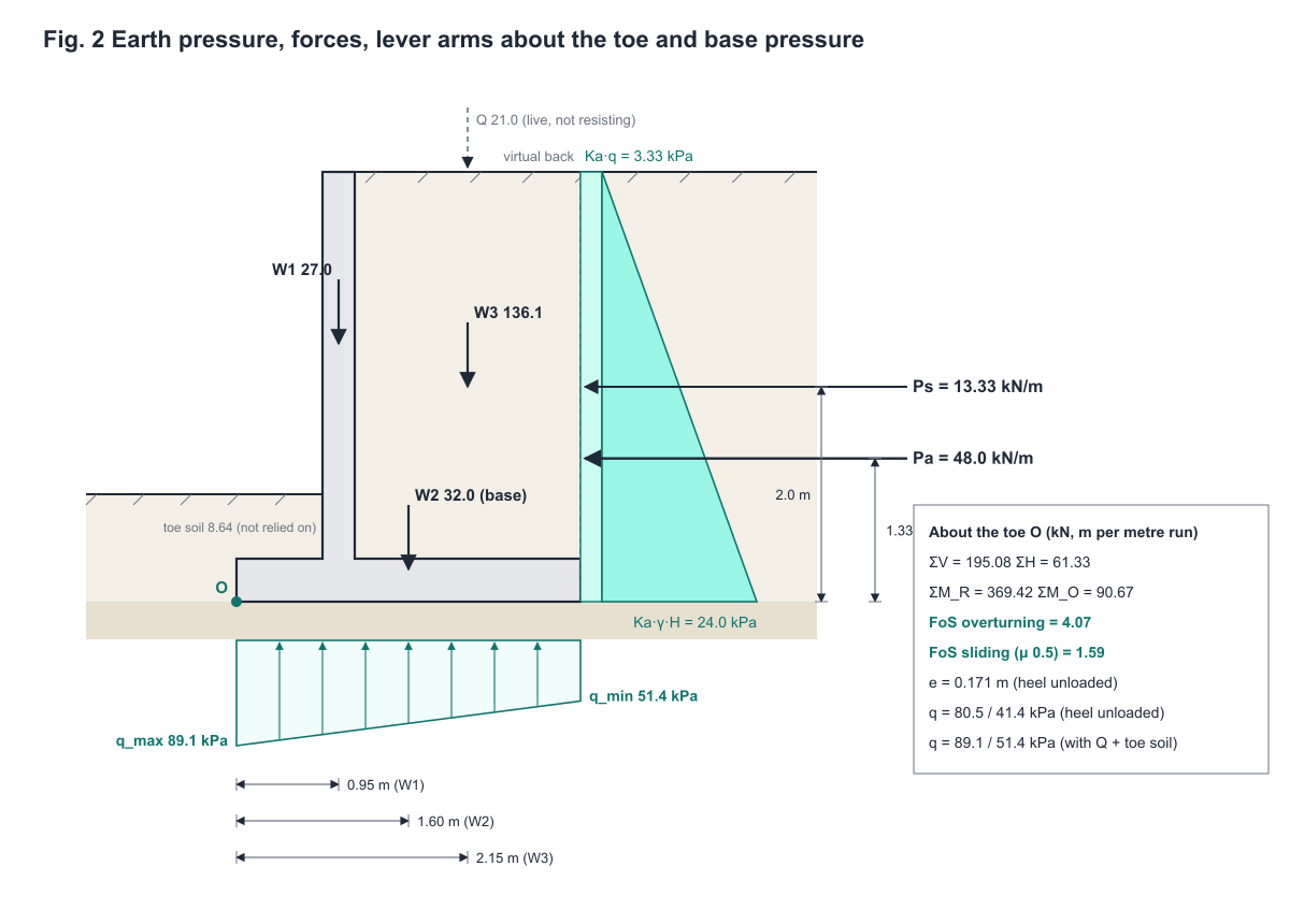
Ka = (1 − sin 30°) / (1 + sin 30°) = 0.5 / 1.5 = 0.3333

Pa = 0.5 × 0.3333 × 18 × 4.0² = 48.00 kN/m      at 4.0/3 = 1.333 m
Ps = 0.3333 × 10 × 4.0        = 13.33 kN/m      at 4.0/2 = 2.000 m
ΣH = 61.33 kN/m

ΣM_O = 48.00 × 1.333 + 13.33 × 2.000 = 64.00 + 26.67 = 90.67 kN·m/m
The pressure at the base of the virtual back is Ka γ H = 24.0 kPa from the soil, plus a uniform Ka q = 3.33 kPa from the surcharge.
Weights and restoring moment about the toe
| Force | Calculation (kN/m) | Value (kN/m) | Lever arm (m) | Moment (kN·m/m) |
|---|---|---|---|---|
| W1 Stem | 0.3 × 3.6 × 25 | 27.00 | 0.8 + 0.15 = 0.95 | 25.65 |
| W2 Base slab | 3.2 × 0.4 × 25 | 32.00 | 3.2 / 2 = 1.60 | 51.20 |
| W3 Soil over heel | 2.1 × 3.6 × 18 | 136.08 | 1.1 + 2.1/2 = 2.15 | 292.57 |
| Total resisting | 195.08 | 369.42 | ||
| Live surcharge on heel (not resisting) | 10 × 2.1 | 21.00 | 2.15 | 45.15 |
| Soil over toe (not relied on) | 0.8 × 0.6 × 18 | 8.64 | 0.40 | 3.46 |
| Pa (driving) | see above | 48.00 | 1.333 | 64.00 |
| Ps (driving) | see above | 13.33 | 2.000 | 26.67 |
Overturning check
FoS_OT = 369.42 / 90.67 = 4.07  ≥ 2.0  ✓

IS 456 cl. 20.1:  0.9 × 369.42 = 332.5  ≥  1.2 × 64.00 + 1.4 × 26.67 = 114.1  ✓
Sliding check, and why the heel is 2.1 m
FoS_SL = 0.5 × 195.08 / 61.33 = 97.54 / 61.33 = 1.59  ≥ 1.5  ✓

IS 456 cl. 20.2 (0.9 × dead load):
FoS = 0.9 × 195.08 × 0.5 / 61.33 = 87.79 / 61.33 = 1.43  ≥ 1.4  ✓
Clause 20.2 governs here. A factor of 1.4 on only 0.9 of the dead load is the same as 1.4 / 0.9 = 1.56 on the full weight, which is stricter than the 1.5 practice value. Here is how the heel was sized. With toe 0.8 m, stem 0.3 m and heel L, the resisting weight is
ΣV = 27 + 25 × 0.4 × (1.1 + L) + 18 × 3.6 × L = 38 + 74.8 L

Practice 1.5:    0.5 ΣV ≥ 1.5 × 61.33   →  ΣV ≥ 184.0  →  L ≥ 1.95 m
cl. 20.2 (1.4):  0.45 ΣV ≥ 1.4 × 61.33  →  ΣV ≥ 190.8  →  L ≥ 2.04 m   → use 2.1 m
A shear key, counted passive resistance or a rougher base (higher μ) would each shorten the heel.
Base pressure and eccentricity
The engine checks two load cases and reports the worse of each. The first leaves the surcharge off the heel. The second adds the surcharge weight and the soil over the toe, because extra weight raises the bearing pressure.
Case 1, heel unloaded:
ΣV = 195.08 kN/m,  ΣM_net = 369.42 − 90.67 = 278.75 kN·m/m
x̄ = 278.75 / 195.08 = 1.429 m,  e = 1.600 − 1.429 = 0.171 m  < B/6 = 0.533 m  ✓
q = (195.08 / 3.2) × (1 ± 6 × 0.171 / 3.2) = 60.96 × (1 ± 0.321) = 80.5 / 41.4 kPa

Case 2, with surcharge and soil over the toe:
ΣV = 195.08 + 21.00 + 8.64 = 224.72 kN/m
ΣM_net = 278.75 + 45.15 + 3.46 = 327.36 kN·m/m
x̄ = 1.457 m,  e = 0.143 m
q = 70.23 × (1 ± 0.269) = 89.1 / 51.4 kPa   ← governs;  89.1 ≤ 180 kPa ✓
The engine also checks ultimate bearing using Meyerhof's equation with inclination factors on the effective width B′ = B − 2e = 2.858 m (IS 6403). It gives q_ult = 335 kPa. The pressure to compare it with is the load spread over that same effective width, V / B′ = 195.08 / 2.858 = 68.26 kPa, so q_ult / q = 335.2 / 68.26 = 4.91, which exceeds the required 2.5. (Dividing by the 80.5 kPa trapezoidal peak instead would mix two methods.) The global (Bishop) slip-circle check gives FoS = 2.00 against a target of 1.5.
Stem design (IS 456 limit state)
The stem cantilevers from the top of the base, so its span is hs = 3.6 m, not H. The factored load combination is 1.5(DL + EP + LL):
M_service = Ka γ hs³ / 6 + Ka q hs² / 2
          = 0.3333 × 18 × 3.6³ / 6 + 0.3333 × 10 × 3.6² / 2
          = 46.66 + 21.60 = 68.26 kN·m/m
Mu = 1.5 × 68.26 = 102.38 kN·m/m

d = 300 − 50 − 16/2 = 242 mm
Mu,lim = 0.133 × 25 × 1000 × 242² = 194.7 kN·m/m  > Mu  → singly reinforced

4.6 Mu / (fck b d²) = 4.6 × 102.38×10⁶ / (25 × 1000 × 242²) = 0.3216
Ast = 0.5 × (25/500) × (1 − √(1 − 0.3216)) × 1000 × 242 = 1067 mm²/m

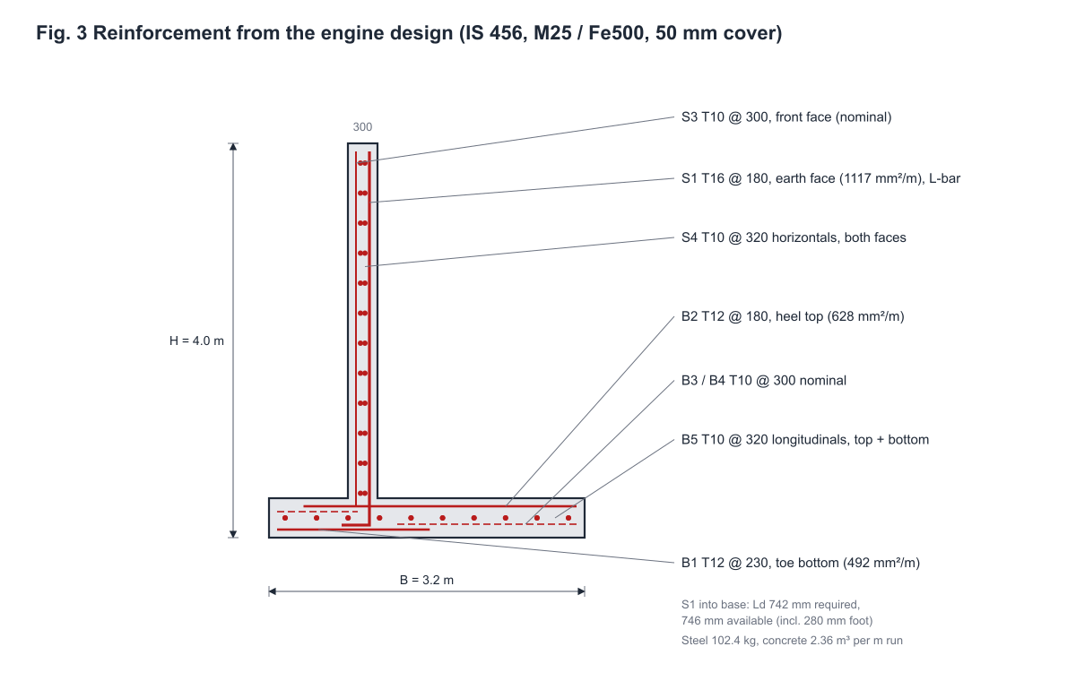
Provide T16 @ 180 mm c/c → 1117 mm²/m  (earth face)
Shear at d = 0.242 m above the base, where the depth of soil above is z = 3.6 − 0.242 = 3.358 m:
Vu = 1.5 × (0.5 × 0.3333 × 18 × 3.358² + 0.3333 × 10 × 3.358)
   = 1.5 × (33.83 + 11.19) = 67.5 kN/m
τv = 67.5 × 10³ / (1000 × 242) = 0.279 MPa
pt = 100 × 1117 / (1000 × 242) = 0.462 %  →  τc (M25, Table 19) = 0.36 + (0.212/0.25) × 0.13 = 0.470 MPa
k = 1.0 (D = 300 mm, cl. 40.2.1.1);  τv = 0.279 < 0.470 MPa  ✓  no shear steel
Heel and toe
The heel carries the downward weight of the soil and concrete on it, minus the soil pressure underneath. The worst moment does not come from the 1.5 load case. It comes from 0.9DL + 1.5EP + 1.5LL, where the low dead-load factor lowers the soil pressure under the heel. In that case ΣV = 175.6 kN/m, e = 0.481 m, and the soil pressure under the base runs from 104.3 kPa at the toe to 5.4 kPa at the heel, which is 70.3 kPa at the back face of the stem:
Downward on the heel = 0.9 × (18 × 3.6 + 25 × 0.4) = 67.32 kPa
Mu = 67.32 × 2.1² / 2 − [5.4 × 2.1² / 2 + (70.3 − 5.4) × 2.1² / 6]
   = 148.44 − 59.61 = 88.8 kN·m/m   (tension at the top)
Ast,req = 616 mm²/m → T12 @ 180 (628 mm²/m), top of heel
The toe bends upward under the 1.5 case. Soil pressure is 133.6 kPa at the toe edge and 119.5 kPa at the stem face. The downward load is 1.5 × (25 × 0.4 + 18 × 0.6) = 31.2 kPa:
Mu = 119.5 × 0.8²/2 + (133.6 − 119.5) × 0.8²/3 − 31.2 × 0.8²/2 = 31.3 kN·m/m
Ast,min = 0.12 % × 1000 × 400 = 480 mm²/m governs → T12 @ 230 (492 mm²/m), bottom of toe
Engine results
The cantilever retaining wall design tool returned the same numbers. All 30 checks pass (from worked_example.txt):
| Check | Demand | Capacity | Ratio |
|---|---|---|---|
| Overturning (FoS 2.0) | 181.3 kN·m/m | 369.4 kN·m/m | 0.49 |
| Sliding (FoS 1.5) | 92.0 kN/m | 97.5 kN/m | 0.94 |
| Overturning, IS 456 cl. 20.1 | 114.1 | 332.5 | 0.34 |
| Sliding, IS 456 cl. 20.2 (FoS 1.4) | 85.9 | 87.8 | 0.98 |
| Bearing q_max vs SBC | 89.1 kPa | 180 kPa | 0.49 |
| Eccentricity e vs B/6 | 0.171 m | 0.533 m | 0.32 |
| Ultimate bearing (FS 2.5) | 170.7 kPa | 335.2 kPa | 0.51 |
| Global stability (Bishop) | 1.50 | 2.00 | 0.75 |
| Stem flexure, T16 @ 180 | 102.4 kN·m/m | 106.6 kN·m/m | 0.96 |
| Stem shear at d | 67.5 kN/m | 113.7 kN/m | 0.59 |
| Stem crack width (Annex F) | 0.281 mm | 0.30 mm | 0.94 |
| Stem deflection | 13.5 mm | 14.4 mm (L/250) | 0.94 |
| Stem bars into base, Ld | 742 mm | 746 mm | 0.99 |
| Heel flexure, T12 @ 180 | 88.8 kN·m/m | 90.5 kN·m/m | 0.98 |
| Toe flexure, T12 @ 230 | 31.3 kN·m/m | 71.4 kN·m/m | 0.44 |
The stem fails the deemed-to-satisfy span/depth rule: L/d = 3600/242 = 14.9, against 7 × kt = 7.7. When that happens, the engine calculates the long-term tip deflection of the cracked cantilever instead (Annex C). Here that is 13.5 mm, within span/250 = 14.4 mm. Distribution steel is T10 @ 320 mm on each face, and the front face carries nominal T10 @ 300 mm verticals. Quantities per metre run are 2.36 m³ of concrete and 102.4 kg of steel.
We proportioned this wall by hand. The engine's optimiser, run on the same loads, found a cheaper wall that passes every check: B = 2.70 m, toe 0.25 m, heel 2.15 m, base 450 mm, stem 300 mm. At its default Indian rates (concrete ₹5,000/m³, steel ₹60/kg, excavation ₹250/m³), that wall costs ₹17,277 per metre, against about ₹18,900 for our 3.2 m base.
IS 456 clause reference for retaining wall design
| Check | Reference | Value in this example |
|---|---|---|
| Overturning | IS 456 cl. 20.1: restoring 0.9 DL ≥ 1.2 DL + 1.4 LL overturning | 332.5 ≥ 114.1 |
| Sliding | IS 456 cl. 20.2: FoS ≥ 1.4 with 0.9 DL | 1.43 |
| Practice factors of safety | 2.0 overturning, 1.5 sliding (1.5 / 1.2 with earthquake) | 4.07 / 1.59 |
| Load combinations | IS 456 Table 18 | 1.5(DL+EP+LL); 0.9DL+1.5EP+1.5LL |
| Flexure | IS 456 cl. 38.1, Annex G | Stem Ast 1067 mm²/m |
| One-way shear | IS 456 cl. 22.6.2, 40.1, 40.2.1.1, Table 19 | τv 0.279 < τc 0.470 MPa |
| Minimum steel | IS 456 cl. 26.5.2.1 (0.12 % bD, HYSD) | 360 / 480 mm²/m |
| Bar spacing | IS 456 cl. 26.3.3(b): ≤ 3d or 300 mm | 180 mm |
| Crack width | IS 456 cl. 35.3.2, Annex F | 0.281 ≤ 0.3 mm |
| Deflection | IS 456 cl. 23.2, Annex C | 13.5 ≤ 14.4 mm |
| Development length | IS 456 cl. 26.2.1 | 742 ≤ 746 mm |
| Ultimate bearing | IS 6403 (Meyerhof), FS 2.5 | q_ult 335 kPa |
| Seismic earth pressure | IS 1893 (Part 3), Mononobe-Okabe | Not applied here |
The engine also cites IS 14458 (Part 2), the guidelines for retaining walls in hill areas, for its global-stability target of 1.5.
IS 456 vs ACI 318 vs Eurocode: factors of safety or partial factors
The three codes reach a safe wall by different routes. CivilTech Studio implements them as follows:
| IS 456 | ACI 318-19 | EN 1992-1-1 + EN 1997-1 | |
|---|---|---|---|
| Overturning | FoS 2.0 on characteristic loads, plus cl. 20.1 | FoS 1.5 (IBC 2021 §1807.2.3) | EQU partial factors: γG,dst 1.1, γG,stb 0.9, γQ 1.5, γφ′ 1.25 |
| Sliding | FoS 1.5, plus cl. 20.2 (1.4 with 0.9 DL) | FoS 1.5 | Design Approach 1, Combinations 1 and 2 |
| With earthquake | 1.5 / 1.2 | 1.1 with 0.7E | γ = 1.0 on actions, γφ′ 1.25 (EN 1998-5) |
| Bearing | q_ult / q_max ≥ 2.5 | q_ult / q_max ≥ 3.0 | EN 1997-1 Annex D resistance, DA1 |
| Member combinations | 1.5(DL+EP+LL); 0.9DL+1.5EP+1.5LL | 1.4D+1.6H; 1.2D+1.6H+1.6L; 0.9D+1.6H | 1.35G+1.5Q; G favourable at 1.0 |
| Global FoS override | Yes | Yes | No, because there is no global FoS |
We ran the same 3.2 m wall under all three codes. It passes IS 456. Under ACI 318 it fails only on stem deflection (ratio 2.16). The 300 mm stem is thinner than ACI's cantilever minimum of about 400 mm (ℓ/10 × (0.4 + fy/700) for ℓ = 3.6 m), so the engine falls back to a calculated long-term deflection, which comes out more than twice the ℓ/240 limit. Under Eurocode it fails sliding in DA1 Combination 2 (ratio 1.03), where tan φ′ and μ are both divided by 1.25. One wall, three verdicts: you cannot carry a design from one code to another unchanged.
Rankine vs Coulomb vs Mononobe-Okabe earth pressure
| Theory | When to use | Ka for φ = 30°, level fill |
|---|---|---|
| Rankine | Smooth vertical back. Conservative and standard for cantilever walls, since the earth pressure acts on the vertical plane through the heel | 0.333 |
| Coulomb | Includes wall friction δ, a battered back and backfill slope. The thrust is inclined, and its vertical part helps resist at the heel | 0.297 with δ = 20° (horizontal part 0.279) |
| Mononobe-Okabe | Pseudo-static seismic pressure with horizontal and vertical seismic coefficients kh and kv | 0.397 with kh = 0.1, δ = 0 (0.366 with δ = 20°) |
In the engine, the Mononobe-Okabe increment ΔPae = Pae − Pa acts at 0.6H′ (Seed and Whitman) rather than H/3. The inertia of the wall and the heel soil (kh × W) is added. The weights are multiplied by (1 − kv), and kv is checked in both directions. For sloping backfill, the thrust acts on a virtual back of height H′ = H + heel × tan β.
Common mistakes in retaining wall calculations
- Measuring H from the front ground. In our wall the exposed height is 3.0 m. Using 3.0 m instead of 4.0 m cuts Pa from 48 to 27 kN/m (−44 %) and the earth moment by 58 %.
- Counting live surcharge as stabilising. The 21 kN/m of surcharge on the heel would add 45 kN·m/m of restoring moment that may not exist when the wall is loaded. Count it in bearing, never in overturning or sliding.
- Relying on soil over the toe or on full passive resistance. Trenches for drains and cables often remove it. Treat passive as a bonus: halve it, drop the top 0.5 m, or use a shear key.
- Ignoring water. If the weep holes clog and the water table rises to the top of the fill, the same wall's overturning FoS drops from 4.07 to 1.33 and its sliding FoS from 1.59 to 0.62. The water thrust is 78.5 kN/m and the base uplift 62.8 kN/m. Typical Indian site practice is a graded filter or a 300 mm granular drainage layer behind the stem, with 75 to 100 mm PVC weep holes at about 1.0 to 1.5 m centres both ways. A perforated drain at the heel helps too. If you cannot guarantee drainage, design for the water.
- Using H for the stem moment. The stem spans hs = H − base thickness. Using 4.0 m instead of 3.6 m would overstate Mu by about 33 % (90.7 against 68.3 kN·m/m at service).
- Checking the heel only under the full 1.5 load case. In our wall, 0.9DL + 1.5EP + 1.5LL gives the larger heel moment (88.8 against 83.3 kN·m/m).
- Forgetting the anchorage of the stem bars into the base. In this example, the development length governs at a ratio of 0.99. A thinner base would need a longer foot on the L-bars.
How CivilTech Studio does this
The retaining wall design module runs the calculation above on one force model. Every action has a point of application measured from the toe, and the same forces feed the stability checks, the member design and the drawn stability diagram.
- Codes. IS 456, ACI 318-19 or EN 1992-1-1 with EN 1997-1. A compare drawer re-runs the same wall under each code.
- Earth pressure. Rankine, Coulomb with wall friction, or Mononobe-Okabe seismic pressure. It also handles sloping backfill, a battered stem front face, a water table with uplift, and water on the toe side.
- Stability. Overturning, sliding, allowable and ultimate bearing (Meyerhof), eccentricity, uplift where there is water, and a Bishop slip-circle global check. Live surcharge drives but never resists. Passive resistance is optional and halved, with the top 0.5 m ignored, and a shear key brings it in automatically.
- Members. Stem, heel, toe and key are designed under the code's own load combinations, with favourable dead load factored as favourable. Each check reports demand ÷ capacity with its clause and the working.
- Design or check mode. Let the engine pick the bars, or enter your own and have them verified.
- Detailing. Curtailment, development of the stem bars into the base, laps, distribution and front-face bars, and a full bar schedule. Pair it with the BBS cutting length calculator for site take-off.
- Serviceability. Crack width and stem deflection: the span/depth rule first, then the long-term tip deflection.
- Optimiser. It searches base width, toe/heel split, base and stem thickness, and optionally a shear key. It returns the least-cost wall that passes every check, plus up to 15 alternatives, in about 3 to 4 seconds.
- Outputs. PDF and Excel reports, and a DXF section drawing with bars and dimensions.
For the foundation inputs, the bearing capacity calculator helps you set a realistic SBC, and the rebar development length tool checks laps and anchorage on their own. Below-ground walls propped by floor slabs behave differently from cantilevers; use basement wall design for those.
FAQ
What is the factor of safety for a retaining wall as per IS code?
IS 456 cl. 20.1 requires the restoring moment from 0.9 × dead load to be at least 1.2 × the dead-load overturning moment plus 1.4 × the imposed-load overturning moment. Clause 20.2 requires a sliding FoS of at least 1.4 using 0.9 × dead load. Common Indian practice also requires FoS 2.0 against overturning and 1.5 against sliding on characteristic loads, relaxed to 1.5 and 1.2 with earthquake.
How do you calculate the active earth pressure on a retaining wall?
Use Pa = 0.5 × Ka × γ × H², acting at H/3 above the base underside, with Ka = (1 − sin φ)/(1 + sin φ) for Rankine conditions. A uniform surcharge q adds Ka × q × H, acting at H/2. For φ = 30°, γ = 18 kN/m³ and H = 4.0 m, Pa = 48 kN/m.
What should the base width of a cantilever retaining wall be?
Start at 0.5H to 0.7H, then size the heel so that sliding passes. With μ = 0.5, a 10 kPa surcharge and no shear key, our 4.0 m wall needed B = 3.2 m (0.8H). The optimiser found that 2.70 m works with a short toe and a thicker base.
When is a shear key needed in a retaining wall?
Use one when sliding governs and widening the base becomes uneconomic, which is typical on clayey or smooth founding strata with a low μ. The key mobilises passive resistance in front of it down to its bottom. Halve that passive resistance in design, because it needs movement to develop.
Why is surcharge not considered in the stability of a retaining wall?
It is considered, but only where it is unfavourable. A live surcharge's thrust always drives the wall, and its weight raises the bearing pressure. Its weight on the heel is not counted as resisting overturning or sliding, because the load may be absent or may sit just beyond the heel.
Is Rankine or Coulomb better for retaining wall design?
Rankine on a vertical plane through the heel is the usual and conservative choice for cantilever walls. Coulomb suits gravity walls or battered backs where wall friction is reliable. It gives a lower Ka and an inclined thrust whose vertical part helps resist.
Do weep holes change the design calculation?
They decide whether you may design the wall as drained. A wall with a working filter and weep holes is designed for earth pressure alone. If drainage can fail, design for a water table: in our example, full water pressure would cut the sliding FoS from 1.59 to 0.62.
Educational reference. Always verify against the governing code and your project specification.