#rcc#preliminary-design#is-456#thumb-rules#house-construction
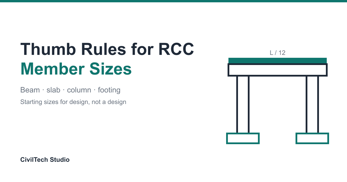
Thumb Rules for Column, Beam and Slab Size (RCC Preliminary Design)
Starting sizes for RCC beams, slabs, columns and footings from IS 456-based thumb rules, with a worked house-frame example and a ready table. Not a design.
Updated 4 Nov 20269 min read
 Try it free: open this worked example in Foundation DesignOpen →
On this page
Before any structural analysis can start, every beam, slab, column and footing needs a size. You cannot work out self-weight, stiffness or moments without one. Engineers start from thumb rules: span-to-depth ratios and load-to-area rules that give a reasonable first size in a few seconds.
This guide sets out the thumb rules used by the free preliminary sizing calculator, where they come from in IS 456:2000, and a worked example for a typical house frame. Read every number here as a starting size for design, not a design. Each one still has to be checked for strength, deflection and detailing.
The thumb rules
Beams
Overall depth D ≈ L / 12   (simply supported)
Overall depth D ≈ L / 15   (continuous)
Width b ≈ D / 2, but not less than 230 mm
D is rounded up to the next 25 mm, and b likewise. IS 456 Cl 23.2.1 gives the related basic span to effective depth ratios: 20 for simply supported and 26 for continuous members.
One-way slabs
d ≈ L / (20 × 1.4)   (simply supported)
d ≈ L / (26 × 1.4)   (continuous)
t = d + 25 mm, not less than 100 mm, rounded up to 10 mm
The Cl 23.2.1 ratios 20 and 26 are span to effective depth, so they set d, not t. The 1.4 is an assumed modification factor (IS 456 Fig 4) for a lightly reinforced slab, about 0.3 % steel.
Cantilevers (beams and slabs)
For a cantilever the Cl 23.2.1 basic ratio of 7 is applied to the effective depth d, and an allowance for cover and bars is added:
d ≈ L / 7
Beam:  D = d + 50 mm
Slab:  t = d + 25 mm
Two-way slabs
- Shorter span Lx up to 3.5 m: Cl 24.1 note 2 allows span to overall depth of 35 (simply supported) or 40 (continuous), multiplied by 0.8 for Fe 415 steel, for live loads up to 3 kN/m². That gives t ≈ Lx/28 or Lx/32.
- Lx over 3.5 m: the Cl 23.2.1 basic ratio (20 or 26) is used with an assumed modification factor of 1.4 for a lightly reinforced slab: d ≈ Lx/(20 × 1.4) or Lx/(26 × 1.4), then t = d + 25 mm.
Columns
The column is sized as a short, axially loaded member to Cl 39.3, with a load factor of 1.5, 1% longitudinal steel and Fe 415:
Pu = 1.5 × P
Ag = Pu / (0.4 fck (1 − p) + 0.67 fy p),   p = 0.01, fy = 415
Side = √Ag, rounded up to 25 mm, not less than 230 mm
P is the service (unfactored) axial load on the column.
Isolated footings
Plan area A ≈ 1.1 × P / q
Side = √A, rounded up to 0.05 m
q is the safe bearing capacity of the soil (kN/m²). The factor 1.1 is the usual 10% allowance for the footing's own weight.
Worked example: a typical house frame
A two-storey RCC house has these members. Concrete for the column is M20.
| Member | Input |
|---|---|
| Main beam | continuous, span 4.5 m |
| Floor slab panel | two-way, continuous, shorter span 3.6 m |
| Balcony slab | cantilever, 1.2 m |
| Corner column | service load P = 650 kN, M20 |
| Column footing | P = 650 kN, SBC = 120 kN/m² |
1. Beam. D = 4500 / 15 = 300 mm. b = 300 / 2 = 150 mm, below the 230 mm minimum, so b = 230 mm. Starting size 230 × 300 mm. If the same beam were simply supported, D = 4500 / 12 = 375 mm, giving 230 × 375 mm.
2. Two-way slab. Lx = 3.6 m is over 3.5 m, so d = 3600 / (26 × 1.4) = 3600 / 36.4 = 99 mm, and t = 99 + 25 = 124 mm, rounded up to 130 mm.
For comparison, a 3.2 m panel falls under Cl 24.1 note 2: t = 3200 / 32 = 100 mm. The rule changes at 3.5 m, and so does the result: a 3.5 m continuous panel gets 110 mm and a 3.6 m panel 130 mm.
3. Balcony slab. d = 1200 / 7 = 171 mm, t = 171 + 25 = 196 mm, rounded up to 200 mm. The basic ratio of 7 is used without any modification factor, so this is a cautious starting point; the deflection check in the design may justify a thinner slab.
4. Column.
- Pu = 1.5 × 650 = 975 kN
- 0.4 × 20 × (1 − 0.01) + 0.67 × 415 × 0.01 = 7.920 + 2.781 = 10.700 N/mm²
- Ag = 975,000 / 10.700 = 91,117 mm²
- √91,117 = 302 mm, rounded up to 325 mm
Starting size 325 × 325 mm. In M25 the same load gives 300 × 300 mm.
5. Footing. A = 1.1 × 650 / 120 = 5.96 m². √5.96 = 2.44 m, rounded up to 2.45 m. Starting size 2.45 × 2.45 m.
These sizes go into the analysis model. The design then decides whether they stay, grow or shrink.
Reference table: starting sizes by span and load
Beams and slabs, from the rules above:
| Span (m) | Beam, simply supported | Beam, continuous | One-way slab, continuous | Two-way slab, continuous (Lx) |
|---|---|---|---|---|
| 3.5 | 230 × 300 mm | 230 × 250 mm | 130 mm | 110 mm |
| 4.0 | 230 × 350 mm | 230 × 275 mm | 140 mm | 140 mm |
| 4.5 | 230 × 375 mm | 230 × 300 mm | 150 mm | 150 mm |
| 5.0 | 230 × 425 mm | 230 × 350 mm | 170 mm | 170 mm |
| 6.0 | 250 × 500 mm | 230 × 400 mm | 190 mm | 190 mm |
| 7.0 | 300 × 600 mm | 250 × 475 mm | 220 mm | 220 mm |
Square columns and footings, by service load (footings at SBC 150 kN/m²):
| Service load P (kN) | Column, M20 | Column, M25 | Footing, SBC 150 |
|---|---|---|---|
| 300 | 230 × 230 mm | 230 × 230 mm | 1.50 × 1.50 m |
| 500 | 275 × 275 mm | 250 × 250 mm | 1.95 × 1.95 m |
| 800 | 350 × 350 mm | 325 × 325 mm | 2.45 × 2.45 m |
| 1200 | 425 × 425 mm | 400 × 400 mm | 3.00 × 3.00 m |
| 1600 | 475 × 475 mm | 450 × 450 mm | 3.45 × 3.45 m |
Common mistakes
- Building from the thumb-rule size without a design. These are inputs to the analysis, not outputs from it. A thumb rule knows nothing about the actual loads, moments, deflection or detailing.
- Mixing overall and effective depth. The Cl 23.2.1 ratios (7, 20, 26) apply to the effective depth d. Using them on the overall depth gives a member that is too shallow.
- Sizing columns for axial load only. The column rule assumes a short, axially loaded column. Corner and edge columns carry moments from the beams, and tall columns may be slender; both need a larger section once designed.
- Using factored load for the footing. The footing rule uses the service load P against the safe bearing capacity. Factored loads belong in the column formula, which already applies 1.5.
- Stretching the slab rule past 3.5 m. Cl 24.1 note 2 only covers shorter spans up to 3.5 m and live loads up to 3 kN/m².
- Copying sizes from a neighbouring house. Spans, loads and soil change from plot to plot. Work the rules out for your own building.
How CivilTech Studio does this
The preliminary sizing calculator gives a starting size for five elements: beams, one-way slabs, two-way slabs, square columns and square isolated footings. You choose the element and the support condition (simply supported, continuous or cantilever), and enter the span, or the load, concrete grade (M20, M25 or M30) and SBC. It shows the rule it used and each intermediate value.
It makes no strength, deflection, shear, punching, slenderness or detailing check. Those come next:
- Section design designs the beam or column properly from the starting size.
- Slab design checks the slab thickness for bending, shear and deflection.
- Foundation design designs the footing for bearing, punching and reinforcement.
- The load combination generator lists the factored combinations to check the members against.
FAQ
What is the thumb rule for beam size?
Take the overall depth as span/12 for a simply supported beam and span/15 for a continuous one, and the width as about half the depth, at least 230 mm. A 4.5 m continuous beam starts at 230 × 300 mm; simply supported it starts at 230 × 375 mm.
What is the thumb rule for slab thickness?
For one-way slabs, effective depth d = span/(20 × 1.4) when simply supported and span/(26 × 1.4) when continuous, then add 25 mm for cover; at least 100 mm. A 4 m continuous one-way slab starts at 140 mm. For two-way slabs with a shorter span up to 3.5 m, about Lx/28 (simply supported) or Lx/32 (continuous) under Cl 24.1 note 2. A 3.2 m continuous two-way panel starts at 100 mm.
How do I find column size from load?
Multiply the service load by 1.5, then divide by 0.4 fck (1 − p) + 0.67 fy p with p = 1% and fy = 415, and take the square root for a square column. For 650 kN in M20 this gives Ag = 91,117 mm² and a 325 × 325 mm starting size.
How do I calculate footing size from column load and SBC?
Divide 1.1 times the service load by the safe bearing capacity and take the square root. For 650 kN on soil of 120 kN/m², A = 5.96 m², so start with a 2.45 × 2.45 m footing, then design it for bearing, punching and bending.
Why does the two-way slab thickness jump at 3.5 m?
Because the rule changes. Up to 3.5 m the calculator uses the span to overall depth ratios of Cl 24.1 note 2; beyond it, the basic span to effective depth ratio of Cl 23.2.1 with an assumed modification factor, plus 25 mm for cover. A 3.5 m continuous panel starts at 110 mm and a 3.6 m panel at 130 mm.
Can thumb rules replace structural design?
No. They give a sensible starting size so that the analysis can begin. The final size comes from the design for flexure, shear, deflection, axial load with moments, and detailing to IS 456, and for foundations from the soil investigation.
Educational reference. These are preliminary sizes only. The final member sizes must come from a structural design to IS 456:2000 by a qualified engineer.