#slab-design#is-456#two-way-slab#rcc-design#deflection-check#reinforcement
Two-Way Slab Design (IS 456) — Table 26 & Example
Two way slab design to IS 456 step by step: Table 26 moment coefficients with interpolation, Ast from Annex G, minimum steel, bar spacing, span/depth deflection, shear and corner torsion steel, with a fully checked 4 m × 5 m worked example.
Updated 4 Nov 202617 min read
 Try it free: open this worked example in Slab DesignerOpen →
On this page
- One-way or two-way: which design method applies?
- What governs two way slab design in IS 456
- Step-by-step slab design calculation
- Worked example: 4.0 m × 5.0 m edge panel, 150 mm, M25, Fe 500
- IS 456 vs ACI 318 vs Eurocode 2 in the tool
- Flat slabs and punching shear
- Common mistakes in two-way slab design
- How CivilTech Studio does this
- FAQ
Two Way Slab Design to IS 456: Table 26 Coefficients, Worked Example and Checks
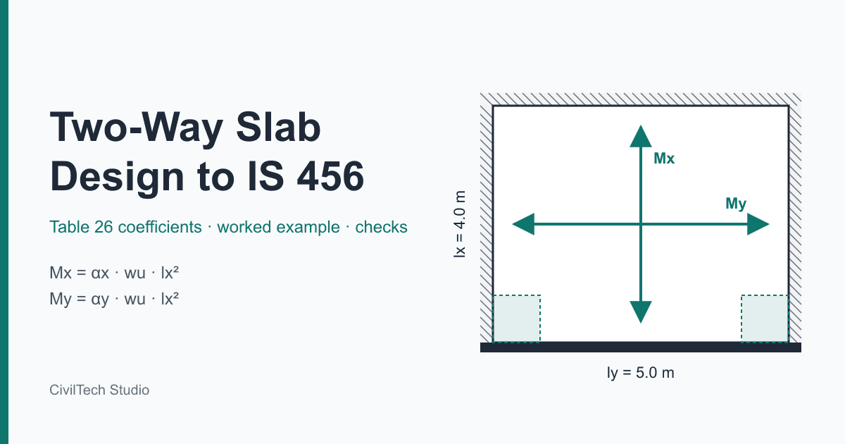
A slab supported on all four sides is designed as two-way when its long span is no more than twice its short span (ly/lx ≤ 2). For two way slab design to IS 456, you take the moment coefficients αx and αy for your panel's edge conditions from Annex D, Table 26, then work out the moments per metre width as Mx = αx·w·lx² and My = αy·w·lx². Steel comes from the Annex G limit-state formula, with at least 0.12 % of the gross section for HYSD bars (Cl 26.5.2.1) and bars no further apart than 3d or 300 mm. You then check span/effective depth on the shorter span (Cl 23.2.1), check shear, and add corner torsion steel at any corner with a discontinuous edge. This guide works through each step and then runs a 4.0 m × 5.0 m, 150 mm residential edge panel through our IS 456 slab design calculator, with every number checked by hand.
By the CivilTech Studio Engineering Team
One-way or two-way: which design method applies?
IS 456 Annex D (Cl D-1.11) draws the line at ly/lx = 2:
- ly/lx > 2: the slab carries load mainly across the short span. Design it as a one-way slab: M = w·l²/8 for a simply supported span, or the Table 12 coefficients for continuous slabs.
- ly/lx ≤ 2, supported on four edges: both directions bend significantly. Design it as a two-way slab using Table 26 (corners held down) or Table 27 (simply supported, corners free to lift).
Table 26 assumes the corners are held down and that torsion reinforcement is provided at the corners. Leave that steel out and the coefficients no longer hold, because the corners lift and the mid-span moments rise.
Annex D also splits each direction into a middle strip (the central three-quarters of the panel width) and two edge strips (one-eighth each). The Table 26 moments apply to the middle strip. The edge strips need only the minimum steel of Cl 26.5.2.1.
What governs two way slab design in IS 456
| Design item | IS 456:2000 provision | What it fixes |
|---|---|---|
| Load factor | Table 18 | wu = 1.5(DL + LL) for the usual gravity case |
| Moment coefficients | Annex D, Table 26 | αx(−), αx(+), αy(−), αy(+) for nine panel types, ly/lx 1.0 to 2.0 |
| Flexural steel | Annex G-1.1 | Ast for a singly reinforced section |
| Minimum steel | Cl 26.5.2.1 | 0.12 % of b·D (HYSD), 0.15 % (mild steel) |
| Maximum bar diameter | Cl 26.5.2.2 | φ ≤ D/8 |
| Maximum bar spacing | Cl 26.3.3(b) | main bars ≤ min(3d, 300 mm); distribution bars ≤ min(5d, 450 mm) |
| Deflection | Cl 23.2.1, Fig. 4; Cl 24.1 | span/d ≤ basic ratio × modification factor, shorter span for two-way slabs |
| Shear | Cl 40, Table 19, Cl 40.2.1.1 | τv ≤ k·τc, with k up to 1.30 for slabs 150 mm or thinner |
| Corner torsion | Annex D-1.8 to D-1.10 | 3/4 or 3/8 of mid-span steel, four layers, over lx/5 |
| Long-term deflection | Cl 23.2, Annex C | total ≤ span/250; deflection after finishes ≤ span/350 or 20 mm |
| Crack width | Cl 35.3.2, Annex F | surface crack width generally ≤ 0.3 mm |
| Loads | IS 875 Parts 1 and 2 | unit weights, finishes, imposed loads |
Step-by-step slab design calculation
1. Factored load. Add up the self-weight (25 kN/m³ × D), floor finish, partitions where needed, and the imposed load from IS 875 Part 2. Then factor the total:
wu = 1.5 × (DL + LL) kN/m²
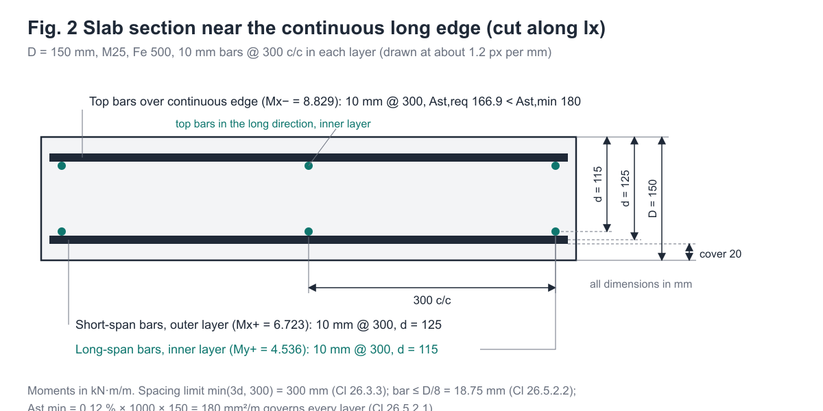
2. Effective depths. The short-span bars carry the larger moment, so they go in the outer layer:
d_short = D − cover − φ/2
d_long  = D − cover − φ − φ/2
3. Panel type and coefficients. Pick the Table 26 case from the number and arrangement of discontinuous edges. Interpolate αx linearly on ly/lx. The long-span αy values do not change with ly/lx.
α = α1 + (α2 − α1) × (r − r1) / (r2 − r1)
4. Moments per metre width.
Mx = αx · wu · lx² My = αy · wu · lx² (both use lx²)
5. Steel area (Annex G-1.1, b = 1000 mm):
Ast = (0.5·fck/fy) × [1 − √(1 − 4.6·Mu/(fck·b·d²))] × b·d
Before using it, confirm Mu < Mu,lim (0.133·fck·b·d² for Fe 500). Slabs almost never get close.
6. Minimum steel and spacing.
Ast,min = 0.0012 × 1000 × D   (HYSD)
s = 1000 × (π·φ²/4) / Ast  ≤ min(3d, 300 mm)
7. Shear. At the support of the short-span strip, Vu ≈ wu·lx/2 per metre. Compare τv = Vu/(b·d) with k·τc from Table 19. Two-way slabs under ordinary floor loads rarely fail this check.
8. Deflection. For two-way slabs, Cl 24.1 uses the shorter span. For spans up to 3.5 m with imposed load up to 3 kN/m², it allows simple span/overall-depth ratios (35 for simply supported, 40 for continuous, multiplied by 0.8 for Fe 415). Beyond that, use Cl 23.2.1: basic ratio (20 simply supported, 26 continuous) × modification factor from Fig. 4, where the factor depends on pt and the steel service stress fs = 0.58·fy·(Ast,req/Ast,prov).
9. Detailing. Provide corner torsion steel, top steel over continuous edges, minimum steel in the edge strips, and keep bars within the D/8 limit.
Worked example: 4.0 m × 5.0 m edge panel, 150 mm, M25, Fe 500
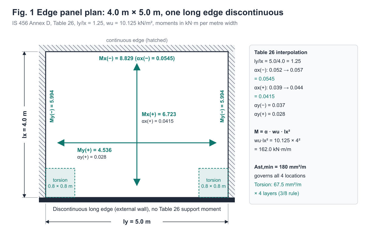
This is a bedroom slab in a residential building. One long edge sits on an external wall (discontinuous) and the other three edges continue into neighbouring panels. Inputs: lx = 4.0 m, ly = 5.0 m, D = 150 mm, clear cover 20 mm (interior, mild exposure), 10 mm bars, M25 concrete, Fe 500 steel. The run used the CivilTech Studio slab design module engine with the same flags as the live API (long-term deflection, crack control, bar schedule and strict serviceability all on). The full script and output are in worked_example.py and worked_example.txt.
Load build-up (IS 875)
| Load | Calculation | kN/m² |
|---|---|---|
| Self-weight | 25 × 0.150 | 3.750 |
| Floor finish + screed | IS 875 Part 1, typical | 1.000 |
| Dead load | 4.750 | |
| Imposed load | IS 875 Part 2, residential floors | 2.000 |
| Service load | 4.75 + 2.00 | 6.750 |
| Factored load wu | 1.5 × 6.75 | 10.125 |
Table 26 coefficients and interpolation
The panel type is "one long edge discontinuous" and ly/lx = 5.0/4.0 = 1.25, which falls midway between the tabulated ratios 1.2 and 1.3:
αx(−) = 0.052 + (0.057 − 0.052) × 0.5 = 0.0545
αx(+) = 0.039 + (0.044 − 0.039) × 0.5 = 0.0415
αy(−) = 0.037   (constant for all ly/lx)
αy(+) = 0.028
Moments, steel and governing values
Common factor: wu·lx² = 10.125 × 4.0² = 162.0 kN·m/m. Effective depths: d_short = 150 − 20 − 5 = 125 mm and d_long = 150 − 20 − 10 − 5 = 115 mm. Ast,min = 0.0012 × 1000 × 150 = 180 mm²/m.
| Location | α | Mu (kN·m/m) | d (mm) | Ast,req (mm²/m) | Ast,min | Governs |
|---|---|---|---|---|---|---|
| Mx(−) over continuous long edge | 0.0545 | 8.829 | 125 | 166.9 | 180 | minimum |
| Mx(+) short-span mid-span | 0.0415 | 6.723 | 125 | 126.3 | 180 | minimum |
| My(−) over short edges | 0.037 | 5.994 | 115 | 122.5 | 180 | minimum |
| My(+) long-span mid-span | 0.028 | 4.536 | 115 | 92.2 | 180 | minimum |
Hand check of the largest value, Mx(−):
4.6 × 8.829e6 / (25 × 1000 × 125²) = 0.10397
√(1 − 0.10397) = 0.94659
Ast = (0.5 × 25/500) × (1 − 0.94659) × 1000 × 125 = 166.9 mm²/m   ✓ engine 166.9
Mu,lim = 0.133 × 25 × 1000 × 125² = 51.95 kN·m/m  ≫ 8.829 → under-reinforced
Minimum reinforcement governs every location. This is normal for a 150 mm residential slab in M25/Fe 500, and it is why many residential slabs end up with one uniform mesh.
Spacing. With 10 mm bars (78.54 mm²), 180 mm²/m works out to 436 mm centres. That is above the Cl 26.3.3(b) limit of min(3 × 125, 300) = 300 mm, so spacing rather than area controls. The engine schedules the widest spacing the clause allows and gives 10 mm @ 300 c/c (262 mm²/m) for each layer. A designer could also detail 10 mm @ 250 (314 mm²/m) or 8 mm @ 250 (201 mm²/m). All three satisfy both area and spacing.
Serviceability and other checks
| Check | Engine result | Limit | Status |
|---|---|---|---|
| Flexural shear, short-span strip | Vu = 20.25 kN/m, τv = 0.162 MPa | k·τc = 1.30 × 0.290 = 0.377 MPa | OK |
| Span/effective depth (lx/d) | 4000/125 = 32.0 | 26 × MF 2.0 = 52.0 | OK |
| Long-term deflection (total) | 1.664 + 1.997 + 0.752 = 4.413 mm | span/250 = 16.0 mm | OK |
| Creep + shrinkage after finishes | 2.749 mm | span/350 = 11.43 mm | OK |
| Bar spacing (crack control) | 300 mm | min(3d, 300) = 300 mm | OK |
| Crack width, Annex F | 0.034 mm at fs = 277 MPa | 0.3 mm | OK |
| Corner torsion steel | 67.5 mm²/m in each of 4 layers | over 800 × 800 mm | required at 2 corners |
| Overall | PASS |
How the numbers come out:
- Shear: τv = 20,250/(1000 × 125) = 0.162 MPa. At pt = 100 × 180/(1000 × 125) = 0.144 %, Table 19 is entered at its lowest row (0.15 %), giving τc = 0.29 MPa for M25. The depth factor k = 1.30 applies because D ≤ 150 mm.
- Deflection: the short span is continuous at one end, so the engine uses the continuous basic ratio of 26. Fig. 4 takes the service stress and pt with the steel actually provided: the design area is the 180 mm²/m minimum and the bars give 262 mm²/m, so fs = 0.58 × 500 × (180/262) = 199 MPa and pt = 100 × 262/(1000 × 125) = 0.209 %. The SP-16 fit of Fig. 4 gives MF = 1/(0.225 + 0.00322 × 199 − 0.625·log10(1/0.209)) = 2.26, which is capped at 2.0. Allowable l/d = 52, actual = 32.
- Long-term deflection: the engine treats a 1 m strip across lx as continuous at one end (coefficient 2.6/384). The service moment is 0.1 × 6.75 × 4² = 10.8 kN·m, below the cracking moment of 0.7√25 × (1000 × 150³/12)/75 = 13.1 kN·m, so the gross section is used. That gives δ = 1.664 mm immediate. Creep adds 0.75 × 1.664 × θ (75 % of the load treated as permanent, the engine default), with θ = 1.6 at 28 days (Cl 6.2.5.1), for 1.997 mm. Shrinkage (εcs = 0.0003, k3 = 0.086) adds 0.752 mm. A two-way panel actually deflects less than an isolated strip, so the strip model is conservative.
- Corner torsion: both corners on the discontinuous long edge have one edge continuous, so D-1.9 calls for 3/8 of the mid-span steel. The engine takes 3/8 × 180 = 67.5 mm²/m over lx/5 = 800 mm, using the provided rather than the required mid-span steel, which is the conservative choice. The two corners where both edges are continuous need none (D-1.10). In practice, a 10 mm @ 300 mesh top and bottom in those corner zones covers it.
- Discontinuous edge: Table 26 gives no negative moment at the external wall, but some restraint still exists. Common practice is top bars of about half the mid-span steel extending 0.1·l into the span. The engine does not schedule these bars, so add them in detailing.
How edge continuity changes the design
Same loads and section, three panel types (engine output):
| Panel type (ly/lx = 1.25) | Mx(−) | Mx(+) | My(−) | My(+) | Max Ast,req | Torsion steel |
|---|---|---|---|---|---|---|
| Interior (all edges continuous) | 7.290 | 5.508 | 5.184 | 3.888 | 137.1 | none |
| One long edge discontinuous | 8.829 | 6.723 | 5.994 | 4.536 | 166.9 | 67.5 mm²/m (3/8) |
| Two adjacent edges discontinuous (corner) | 10.125 | 7.614 | 7.614 | 5.670 | 192.2 | 135.0 mm²/m (3/4) |
Moments in kN·m/m, steel in mm²/m. Only the corner panel's Mx(−) exceeds Ast,min (192.2 > 180). If you design a whole floor with "interior" coefficients, you under-design the corner rooms.
Thinner slab check: with D = 125 mm (dead load recalculated, wu = 9.1875 kN/m²), the same edge panel still passes, with l/d = 40.0 against an allowable of 52.0 (the 10 mm @ 300 bars give fs = 0.58 × 500 × 150/262 = 166 MPa, so MF is again capped at 2.0), and Mx(−) now needs 191.6 mm²/m. For a 4 m short span, 150 mm is still the comfortable choice.
IS 456 vs ACI 318 vs Eurocode 2 in the tool
The slab module has a code selector. For two-way panels it keeps the IS 456 Table 26 moments and changes the resistance side: flexure, minimum steel, shear capacity and the span/depth screen. Same edge panel:
| Item | IS 456 | ACI 318 mode | EC2 mode |
|---|---|---|---|
| Moments | Table 26 | Table 26 | Table 26 |
| Minimum steel rule used | 0.12 % b·D = 180 mm²/m | 0.0018·Ag = 0.0018 × 1000 × 150 = 270 mm²/m | max(0.26·fctm/fyk, 0.0013)·b·d = 166.7 mm²/m |
| Steel reported at Mx(−) | 166.9 req / 180 prov | 159.3 req / 270 prov | 314.2 (bar-selected) |
| Shear capacity | 0.377 MPa | 0.638 MPa | 0.495 MPa |
| Deflection check | l/d 32.0 ≤ 52.0 | h = 150 mm ≥ h_min = 122.4 mm | l/d 32.0 ≤ 33.16 |
| Status | PASS | PASS | PASS |
Two notes on this table. First, the ACI mode uses ACI 318-19's slab minimum of 0.0018·Ag (§8.6.1.1), which is 270 mm²/m here and governs every location. Second, ACI 318 controls deflection with a minimum thickness, not an l/d ratio, and has no modification factor. For a two-way panel on beams, Table 8.3.1.2 gives h_min = ℓn(0.8 + fy/1400)/(36 + 9β) = 5000 × 1.157/(36 + 9 × 1.25) = 122.4 mm, where ℓn is the long span and β = 1.25. That rule assumes stiff edge beams (αfm > 2.0), as the Table 26 coefficients do. With shallow beams, Table 8.3.1.1 applies (ℓn/28.4 = 176 mm here), and the module notes that value too. The EC2 value is a screen built from a basic ratio, not a full code deflection calculation. If you are designing to those codes, use them for comparison and do the final design to the governing code.
Flat slabs and punching shear
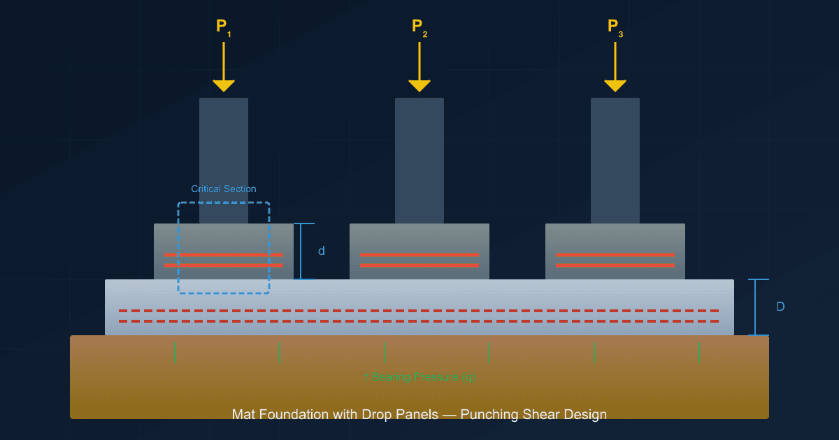
Flat slabs sit on columns without beams, so Table 26 does not apply. Our module designs them by the Direct Design Method of IS 456 Cl 31.4:
- Total static moment: Mo = w·L2·Ln²/8, with Ln not less than 0.65·L1.
- Split along the span: 0.65 negative and 0.35 positive for interior spans; 0.26 / 0.52 / 0.70 for an end span on columns.
- Split across the panel: the column strip takes 75 % of the negative and 60 % of the positive moment.
- Punching shear (Cl 31.6): checked on a perimeter at d/2 from the column face, with b0 = 2[(c1 + d) + (c2 + d)] for an interior column and shorter three-sided or two-sided perimeters at edge and corner columns. The check is τv = Vu/(b0·d) ≤ ks·0.25·√fck, where ks = 0.5 + βc ≤ 1.0. The engine also adds the eccentric-shear stress from any unbalanced moment and checks the peak value.
The engine refuses to run DDM for panels with a long-to-short ratio above 2. It also reminds you that DDM needs at least three continuous spans each way.
Common mistakes in two-way slab design
- Using ly² for My. Both moments use lx², the shorter span. ly enters only through the ratio ly/lx, and lx must be the shorter dimension.
- Applying "interior" coefficients everywhere. Edge and corner panels carry up to 39 % more short-span support moment in this example (10.125 against 7.290 kN·m/m).
- Leaving out corner torsion steel. Table 26 is only valid with it, and without it the corners can lift and crack diagonally.
- Satisfying Ast,min but not spacing. 180 mm²/m with 10 mm bars works out to 436 mm centres, well past the 300 mm limit.
- Checking deflection on the long span or with overall depth in the Cl 23.2.1 ratio. Use lx/d with the effective depth of the outer layer.
- Putting the long-span bars in the outer layer. The short-span moment is larger, so those bars need the bigger d.
- Treating ground-bearing slabs as Table 26 panels. Table 26 is for slabs supported on beams or walls along their edges, not slabs resting on soil.
How CivilTech Studio does this
The two-way slab design calculator handles three slab families in one screen: two-way restrained panels (all nine Table 26 cases), one-way slabs (simply supported wl²/8, or continuous with the Table 12 dead and imposed coefficients split when you enter the factored imposed part), and flat slabs by DDM with punching shear at interior, edge or corner columns. A two-way input with ly/lx > 2 is automatically redesigned as one-way across lx.
Inputs: the factored load (build it up as in the table above) and its imposed part, D, cover, bar diameter, fck, fy, spans and panel type. Optional inputs are the service (unfactored) load, exposure condition and bar spacing. If you leave the service load blank, the engine assumes wu/1.5 and tells you it did.
What the engine returns:
- Table 26 coefficients, and moments with Ast required, minimum and provided at each location
- Flexural shear (Table 19 with the slab depth factor)
- Span/depth deflection with the Fig. 4 modification factor
- Long-term deflection (immediate + creep + shrinkage, Annex C)
- Spacing check (Cl 26.3.3) and Annex F crack width
- Corner torsion steel, and a warning when the bar diameter exceeds D/8
Outputs: a calculation-transparency panel shows each formula with your numbers substituted. The Schedule tab lists bar diameter, spacing, development length (485.5 mm for 10 mm Fe 500 in M25) and lap for each layer. Its cutting-length estimate uses the short span for every layer, so detail the long-span and top bars yourself. Exports give a PDF or Excel report with inputs, moments, Ast per location, checks and design notes. A Compare drawer re-runs the same inputs under IS 456, ACI 318 and Eurocode 2.
To take the slab further, design the supporting beams in the RC section designer, quantify concrete and steel with the RC estimator, convert mm²/m into bar sizes with the rebar area tool, and work out cutting lengths with the BBS cutting length calculator.
FAQ
What is the difference between one-way and two-way slabs in IS 456?
A slab supported on four edges with ly/lx > 2 bends mainly across the short span and is designed as one-way (wl²/8 or Table 12). With ly/lx ≤ 2 it bends both ways and is designed with the Annex D coefficients (Table 26 or 27).
How do you use IS 456 Table 26 moment coefficients?
Pick the row for your panel's edge conditions and interpolate αx linearly between the tabulated ly/lx values. αy is constant. Multiply by wu·lx² for the moment per metre width. For ly/lx = 1.25 with one long edge discontinuous, αx(−) = 0.0545 and αx(+) = 0.0415.
What is the minimum reinforcement in a slab as per IS 456?
Cl 26.5.2.1 requires 0.12 % of the gross area for HYSD bars and 0.15 % for mild steel. For a 150 mm slab that is 180 mm²/m with Fe 500. It applies in both directions and often governs residential slabs.
What is the maximum spacing of main bars in a slab?
For main bars, the lesser of 3d and 300 mm (Cl 26.3.3(b)). For distribution bars, the lesser of 5d and 450 mm. Bar diameter must not exceed D/8 (Cl 26.5.2.2).
How is deflection checked for a two-way slab?
Use the shorter span. For short, lightly loaded spans (up to 3.5 m and 3 kN/m² imposed), Cl 24.1 gives simple span/overall-depth ratios. Otherwise check lx/d against the basic ratio × modification factor of Cl 23.2.1. Our example gives 32.0 against an allowable 52.0.
Is corner torsion reinforcement mandatory?
Yes, wherever Table 26 is used and a corner has a discontinuous edge. You need 3/4 of the mid-span steel where both edges are discontinuous and 3/8 where one is, in four layers over lx/5 from each edge. Corners with both edges continuous need none.
Can a 4 m × 5 m room slab be 125 mm thick?
In our run with M25/Fe 500 and residential loading, a 125 mm edge panel passes with l/d = 40.0 against 52.0, though Mx(−) then needs more than the minimum steel (191.6 mm²/m). 150 mm remains the comfortable choice for a 4 m short span. You can test your own room sizes in the two-way slab calculator.
How is punching shear checked in a flat slab per IS 456?
On a critical perimeter at d/2 from the column face (Cl 31.6): τv = Vu/(b0·d) must not exceed ks·0.25·√fck, with ks = 0.5 + βc ≤ 1. Edge and corner columns have shorter perimeters and carry unbalanced moments, so they usually govern.
Educational reference. Always verify against the governing code and your project specification.