#rcc-beam-design#is-456#limit-state-design#shear-design#doubly-reinforced-beam#structural-design
RCC Beam Design (IS 456) — Worked Example
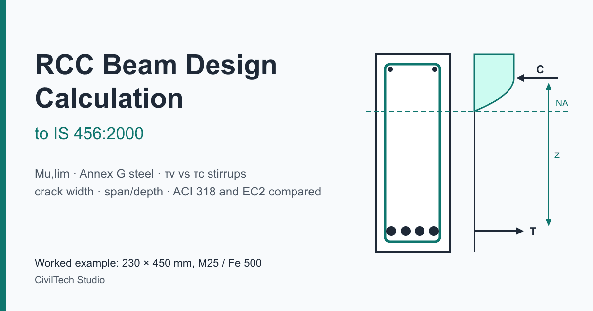
RCC beam design calculation to IS 456 with a fully worked 230 × 450 mm example: Mu,lim, Annex G steel, xu check, τv vs τc stirrups, crack width and span/depth, hand-checked against the CivilTech Studio engine and compared with ACI 318 and EC2.
Updated 4 Nov 202619 min read
 Try it free: open this worked example in Section DesignOpen →
On this page
- What governs RCC beam design in IS 456:2000
- Step-by-step procedure with formulas
- Worked example: 230 × 450 mm floor beam, M25, Fe 500
- When the same beam becomes doubly reinforced
- Same section under ACI 318-19 and Eurocode 2
- Column sections: P–M interaction in one paragraph
- IS 456 clause reference for beam design
- Common mistakes in IS 456 beam calculations
- How CivilTech Studio does this
- FAQ
RCC Beam Design Calculation to IS 456: A Worked Example You Can Check by Hand
An RCC beam design calculation to IS 456 follows six steps. Work out the factored moment and shear. Find the effective depth d. Compare Mu with the limiting moment Mu,lim = 0.36·fck·b·xu,max·(d − 0.42·xu,max). If Mu ≤ Mu,lim the beam is singly reinforced and Ast comes from the Annex G quadratic. If not, it needs compression steel. Then design stirrups by comparing τv = Vu/(b·d) with τc from Table 19, and check deflection (Cl 23.2.1) and crack width (Annex F). For the typical 230 × 450 mm floor beam worked below (M25, Fe 500, 5.0 m simply supported span, Mu = 95 kN·m), the result is 4-16φ bottom bars and 2-legged 8φ stirrups at 300 mm, with every IS 456 strength and serviceability check passing.
By the CivilTech Studio Engineering Team
What governs RCC beam design in IS 456:2000
IS 456 designs beams by the limit state method. The clauses that matter for a rectangular beam are:
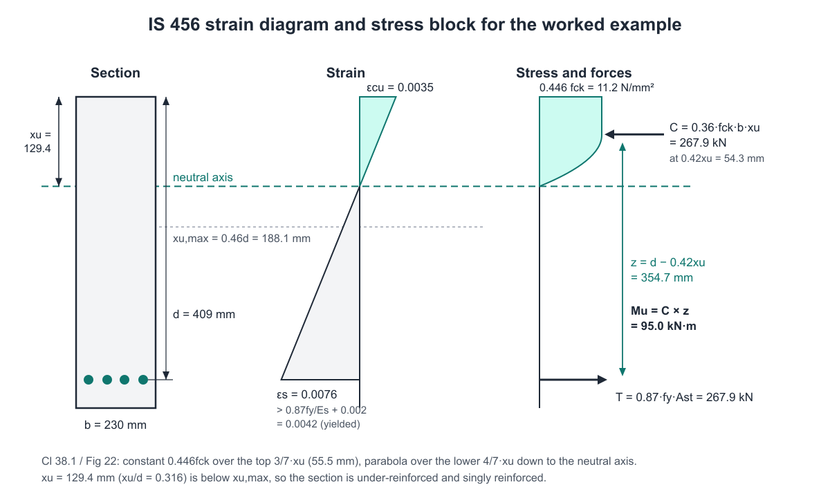
- Cl 38.1, design assumptions for flexure. Plane sections remain plane. The maximum concrete strain is 0.0035. The design stress block is a parabola to a strain of 0.002, then constant at 0.446·fck, so the peak is 0.67·fck/1.5. Steel stress follows the design curve with γm = 1.15. Tensile strength of concrete is ignored. The Cl 38.1 note limits the neutral axis depth to xu,max.
- Annex G. Closed-form moment of resistance for singly reinforced (G-1.1), doubly reinforced (G-1.2) and flanged (G-2) sections.
- Cl 40 with Tables 19 and 20. Nominal shear stress, concrete shear strength τc, the upper limit τc,max, and the design of shear reinforcement.
- Cl 26. Detailing: minimum and maximum steel (26.5.1.1), bar spacing (26.3.2), maximum stirrup spacing (26.5.1.5) and minimum shear reinforcement (26.5.1.6).
- Cl 23.2.1 and Cl 35.3.2 / Annex F. Serviceability through span/effective-depth ratios and the 0.3 mm general crack-width limit.
- Table 18. Load factors. For dead plus imposed load the factor is 1.5.
The value of xu,max/d depends only on steel grade, which is why the limiting moment factor depends on it as well:
| Steel | xu,max/d | Mu,lim / (fck·b·d²) = 0.36·k·(1 − 0.42·k) |
|---|---|---|
| Fe 250 | 0.53 | 0.148 |
| Fe 415 | 0.48 | 0.138 |
| Fe 500 | 0.46 | 0.133 |
Step-by-step procedure with formulas
1. Factored load and actions
   wu = 1.5 (DL + LL)                          [Table 18]
   Simply supported:  Mu = wu·L²/8,  Vu = wu·L/2

2. Effective depth
   d = D − clear cover − stirrup Ø − (main bar Ø)/2

3. Limiting moment
   xu,max = k·d   (k = 0.46 for Fe 500)          [Cl 38.1 note]
   Mu,lim = 0.36·fck·b·xu,max·(d − 0.42·xu,max)  [Annex G-1.1]

4. Singly reinforced (Mu ≤ Mu,lim)
   Mu = 0.87·fy·Ast·d·(1 − Ast·fy/(b·d·fck))     [Annex G-1.1(b)]
   Ast = (0.5·fck/fy)·[1 − √(1 − 4.6·Mu/(fck·b·d²))]·b·d
   xu = 0.87·fy·Ast / (0.36·fck·b)  must be ≤ xu,max

5. Doubly reinforced (Mu > Mu,lim)
   Mu2 = Mu − Mu,lim
   Asc = Mu2 / ((fsc − fcc)·(d − d'))           [Annex G-1.2]
   Ast = 0.36·fck·b·xu,max/(0.87·fy) + Mu2/(0.87·fy·(d − d'))
   fsc from strain 0.0035·(xu,max − d')/xu,max on the design steel curve

6. Steel limits
   Ast,min = 0.85·b·d/fy ;  Ast,max = 0.04·b·D   [Cl 26.5.1.1]

7. Shear
   τv = Vu/(b·d) ≤ τc,max                        [Cl 40.1, Table 20]
   τc from Table 19 for pt = 100·Ast/(b·d)
   Vus = Vu − τc·b·d ;  sv = 0.87·fy·Asv·d / Vus  [Cl 40.4(a)]
   minimum: Asv/(b·sv) ≥ 0.4/(0.87·fy)           [Cl 26.5.1.6]
   maximum: sv ≤ 0.75d and ≤ 300 mm              [Cl 26.5.1.5]
   fy of stirrups is taken as not more than 415 N/mm² [Cl 40.4]

8. Serviceability
   L/d ≤ basic ratio × modification factors       [Cl 23.2.1]
   crack width by Annex F, limit 0.3 mm in general [Cl 35.3.2]
Worked example: 230 × 450 mm floor beam, M25, Fe 500
Inputs and loads
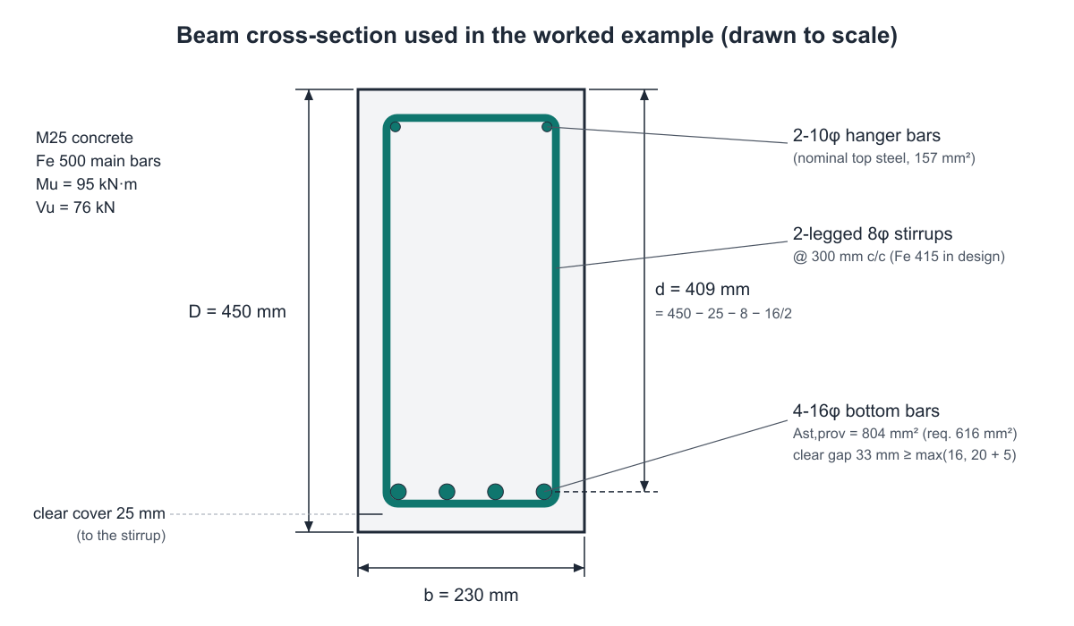
A simply supported floor beam spans 5.0 m (effective span) and carries a 125 mm slab from a 3.0 m tributary width. It is an internal beam in mild exposure, with 25 mm clear cover to the stirrups.
Slab:       (0.125 × 25 + 1.0 finish) kN/m² × 3.0 m   = 12.375 kN/m
Web below slab: 0.23 × (0.45 − 0.125) × 25           =  1.869 kN/m
Dead load DL                                        = 14.244 kN/m
Imposed load LL (2.0 kN/m², residential) × 3.0 m    =  6.000 kN/m
Service load w = 20.244 kN/m      Factored wu = 1.5 × 20.244 = 30.366 kN/m

Mu = 30.366 × 5.0² / 8 = 94.89 kN·m  → use 95 kN·m
Vu = 30.366 × 5.0 / 2  = 75.91 kN    → use 76 kN (support centreline, conservative)
Ms = 20.244 × 5.0² / 8 = 63.26 kN·m  → use 63.3 kN·m (service, for crack width)
These inputs (b = 230, D = 450, cover = 25, M25, Fe 500, Mu = 95, Vu = 76, Ms = 63.3, span 5000 mm, simply supported) were run through the CivilTech Studio IS 456 beam design calculator. The script and its full output are kept with this article.
Flexure: Mu,lim, Ast and the neutral axis check
Effective depth. With 8 mm stirrups and 16 mm bars in one row:
d = 450 − 25 − 8 − 16/2 = 409 mm
The engine starts from an assumed 20 mm bar (d = 407 mm). It then redesigns with the bars it actually picks, so the final d is 409 mm.
Limiting moment (Fe 500).
xu,max = 0.46 × 409 = 188.1 mm
Mu,lim = 0.36 × 25 × 230 × 188.1 × (409 − 0.42 × 188.1)
       = 389 450 N/mm × 330.0 mm = 128.5 kN·m
Check: 0.1336 × 25 × 230 × 409² = 128.5 kN·m
Mu = 95 kN·m is less than 128.5 kN·m, so the beam is singly reinforced.
Required tension steel. Using the Annex G-1.1(b) closed form:
4.6·Mu/(fck·b·d²) = 4.6 × 95×10⁶ / (25 × 230 × 409²) = 0.4543
Ast = (0.5 × 25/500) × [1 − √(1 − 0.4543)] × 230 × 409
    = 0.025 × 0.2613 × 94 070 = 614.5 mm²
The engine solves the same equilibrium directly in xu. It uses 0.36·fck·b·xu·(d − 0.42·xu) = Mu, which gives xu = 129.4 mm and Ast = 2070 × 129.4/435 = 615.8 mm² (reported as 616). The 0.2 % gap is expected. The Annex G closed form rounds the lever-arm coefficient 0.42 × 0.87/0.36 = 1.015 down to 1.0. Both are code formulas.
Neutral axis check. xu/d = 129.4/409 = 0.316, below 0.46, so the steel yields before the concrete crushes. At depth d the steel strain is 0.0035 × (409 − 129.4)/129.4 = 0.0076. That exceeds the yield strain 0.87fy/Es + 0.002 = 0.0042.
Bars. 3-16φ gives 603 mm², which is short of 616. The engine moves to 4-16φ = 804 mm². The clear gap is (230 − 2 × 33 − 4 × 16)/3 = 33 mm, which meets the Cl 26.3.2 minimum of max(16, 20 + 5) = 25 mm. Minimum steel is 0.85 × 230 × 409/500 = 160 mm², so it does not govern. The selector takes the smallest bar size that fits in one row (12 mm needs six bars and only five fit). 2-20φ (628 mm²) would also satisfy Ast with less steel, so choose whichever suits your detailing.
Moment of resistance with the bars provided. The engine re-analyses the section it actually detailed. It integrates the Cl 38.1 parabola–rectangle over the depth by strain compatibility and counts the two 10φ hangers as compression steel. The result is MR = 124.1 kN·m (utilisation 0.765). By hand, ignoring the hangers: xu = 0.87 × 500 × 804/(0.36 × 25 × 230) = 169.0 mm and MR = 349.7 kN × (409 − 71.0) mm = 118.2 kN·m. Adding the hangers lifts this to about 124 kN·m, which agrees with the engine.
Shear: τv vs τc and stirrup spacing
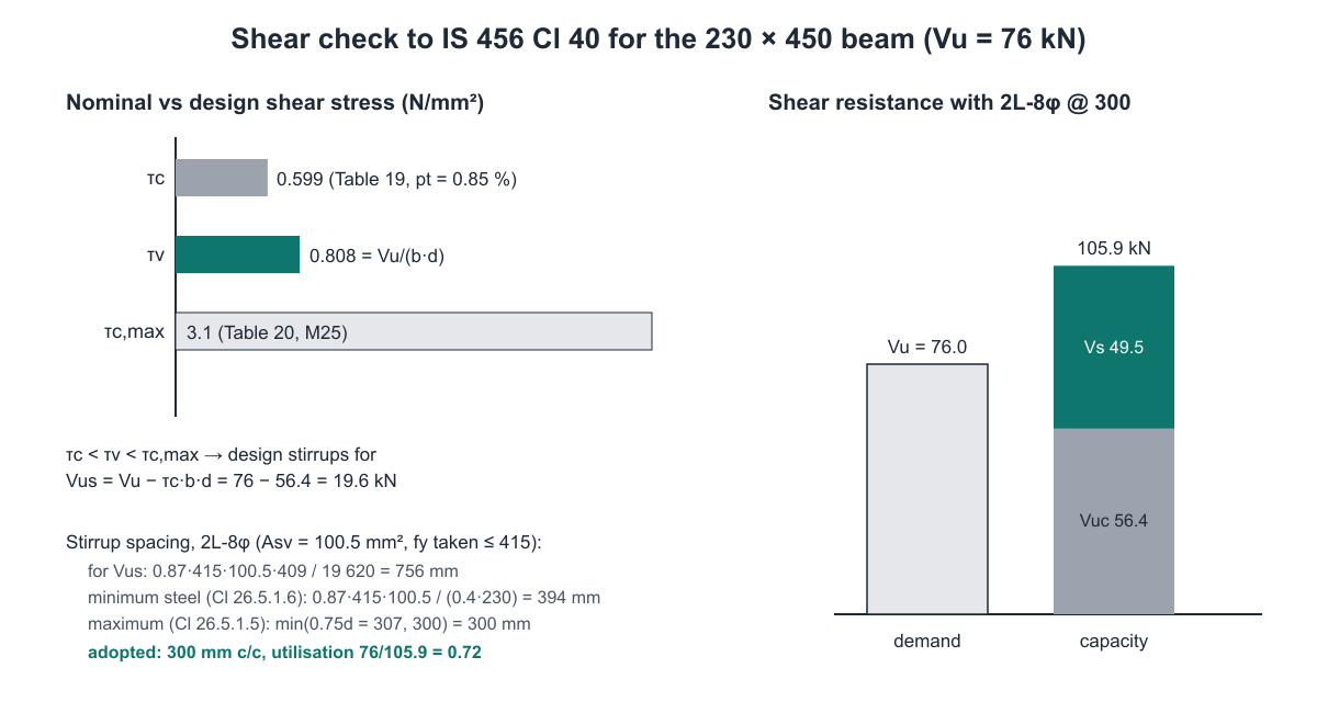
τv     = 76 000 / (230 × 409)                  = 0.808 N/mm²
pt     = 100 × 804 / (230 × 409)                = 0.85 %
τc     = 0.57 + (0.85 − 0.75)/0.25 × 0.07       = 0.599 N/mm²   [Table 19, M25]
τc,max = 3.1 N/mm²                                              [Table 20, M25]
Vuc    = 0.599 × 230 × 409                      = 56.4 kN
Vus    = 76 − 56.4                              = 19.6 kN
τc < τv < τc,max, so shear reinforcement is designed. With 2-legged 8φ stirrups, Asv = 100.5 mm². The stirrup fy is capped at 415 N/mm² under Cl 40.4, even though the main bars are Fe 500.
Spacing for Vus:        0.87 × 415 × 100.5 × 409 / 19 620  = 756 mm
Minimum (Cl 26.5.1.6):  0.87 × 415 × 100.5 / (0.4 × 230)   = 394 mm
Maximum (Cl 26.5.1.5):  min(0.75 × 409 = 307, 300)          = 300 mm
Adopted:                2L-8φ @ 300 mm c/c
Capacity: 56.4 + 0.87 × 415 × 100.5 × 409 / 300 / 1000 = 56.4 + 49.5 = 105.9 kN
Neither the shear demand nor the minimum-steel rule governs here. The 300 mm cap does.
Serviceability: deflection and crack width
Span/effective depth (Cl 23.2.1). The basic ratio for a simply supported beam is 20. The steel stress for the tension modification factor is fs = 0.58 × 500 × 616/804 = 222 N/mm², and with pt = 0.85 % the factor is MFt = 1.11. The engine also applies a compression-steel factor of 1.05 for the two hangers (pc = 0.17 %). The allowed ratio is 20 × 1.11 × 1.05 = 23.5, against 5000/409 = 12.2 provided, so it passes comfortably. Without the hanger factor the limit would be 22.3, and it would still pass.
Crack width (Annex F). The cracked section uses m = 280/(3σcbc) = 280/(3 × 8.5) = 10.98, which gives x = 142.9 mm and lever arm z = 361.4 mm. The steel stress is fs = 63.3×10⁶/(804 × 361.4) = 217.8 N/mm². With acr = 50.0 mm at the bottom corner bar, Eq. F-1 gives:
ε1  = (217.8/200 000) × (450 − 142.9)/(409 − 142.9) = 0.001257
εm  = ε1 − b(h − x)²/(3·Es·As·(d − x))           = 0.001257 − 0.000169 = 0.001088
wcr = 3 × 50.0 × 0.001088 / (1 + 2 × (50.0 − 33)/(450 − 142.9)) = 0.147 mm  ≤ 0.3 mm
Result summary (IS 456)
| Check | Engine output | Hand check | Status |
|---|---|---|---|
| Effective depth d | 409 mm | 450 − 25 − 8 − 8 = 409 | — |
| Mu,lim | 128.5 kN·m | 0.1336·fck·b·d² = 128.5 | Mu = 95 < Mu,lim |
| xu/d | 0.316 | 129.4/409 | ≤ 0.46 OK |
| Ast required | 616 mm² | 615.8 (614.5 by G-1.1(b)) | — |
| Bottom bars | 4-16φ = 804 mm² | 3-16φ = 603 is short | OK |
| MR of provided section | 124.1 kN·m | ≈ 124 (118.2 without hangers) | 0.77 |
| τv / τc / τc,max | 0.808 / 0.599 / 3.1 N/mm² | Table 19 interpolation | Stirrups needed |
| Stirrups | 2L-8φ @ 300 | 300 mm cap governs | OK |
| Shear capacity | 105.9 kN | 56.4 + 49.5 | 0.72 |
| Service steel stress | 217.8 N/mm² | Ms/(As·z) | — |
| Crack width | 0.147 mm | Eq. F-1 | ≤ 0.3 OK |
| L/d | 12.2 vs 23.5 allowed | 20 × 1.11 × 1.05 | OK |
When the same beam becomes doubly reinforced
Raise the load on the same 230 × 450 section to Mu = 150 kN·m and Vu = 110 kN (Ms = 100 kN·m). Mu now exceeds the limit:
d = 407 mm (4-20φ in one row),  xu,max = 0.46 × 407 = 187.2 mm
Mu,lim = 0.36 × 25 × 230 × 187.2 × (407 − 0.42 × 187.2) = 127.3 kN·m
Mu2 = 150 − 127.3 = 22.7 kN·m
d' = 25 + 8 + 12/2 = 39 mm
εsc = 0.0035 × (187.2 − 39)/187.2 = 0.00277  →  fsc = 413 N/mm² (design curve, Fe 500)
fcc = 0.446 × 25 = 11.2 N/mm² (concrete displaced by the bars)
Asc = 22.7×10⁶ / ((413 − 11.2) × (407 − 39)) = 154 mm²
Ast = 0.36 × 25 × 230 × 187.2/435 + 22.7×10⁶/(435 × 368) = 891 + 142 = 1033 mm²
The engine reports the same numbers: Ast,req 1033 mm² (provided 4-20φ = 1257 mm²) and Asc,req 154 mm² (provided 2-12φ = 226 mm²). MR of the detailed section is 161.6 kN·m. Shear: τv = 1.175, τc = 0.715, still 2L-8φ @ 300. Crack width is 0.168 mm. The L/d allowed drops to 20.0 against 12.3 provided. In practice, a beam this far past Mu,lim is usually better deepened than given compression steel. The section optimiser in the calculator is built for that trade-off (see below).
Same section under ACI 318-19 and Eurocode 2
The calculator runs the same beam under all three codes. The table compares the same section with the same input numbers (b = 230, D = 450, cover 25, fck = 25, fy = 500, Mu = 95, Vu = 76, Ms = 63.3, span 5.0 m). All three codes are designed at the depth of the bars actually picked, d = 450 − 25 − 8 − 16/2 = 409 mm. The engine passes fck = 25 to each code as that code's own characteristic strength. It does not convert an IS cube grade to a cylinder strength, so this is a like-for-like comparison of the formulas, not of identical concrete.
| Result | IS 456 | ACI 318-19 | EC2 (EN 1992-1-1) |
|---|---|---|---|
| Limiting moment | Mu,lim = 128.5 kN·m | φMn at tension-controlled limit = 187.6 kN·m | K = 0.167: 160.6 kN·m |
| Ast required | 616 mm² | 555 mm² | 591 mm² |
| Bars chosen | 4-16φ (804) | 3-16φ (603) | 3-16φ (603) |
| Design capacity of bars | 124.1 kN·m | φMn = 102.6 kN·m | 96.7 kN·m |
| Concrete shear stress | τc = 0.599 | φ·0.17√f′c = 0.638 | vRd,c = 0.514 N/mm² |
| Span/depth check | L/d 12.2 ≤ 23.5 | L/h 11.1 ≤ 14.4 | L/d 12.2 ≤ 17.3 |
| Crack width | 0.147 mm (Annex F) | see note | 0.26 mm (Cl 7.3.4) |
Why the numbers differ:
- Stress block and factors. IS 456 uses 0.36·fck·b·xu at 0.42xu with fyd = 0.87fy. ACI uses 0.85f′c over β1·c with fy unfactored and the whole moment multiplied by φ = 0.90. EC2 uses 0.567fck over 0.8x with fyd = fyk/1.15. ACI needs the least steel here because φ = 0.9 on 1.0·fy is more generous than 0.87fy.
- Neutral-axis limits. IS caps xu/d at 0.46 for Fe 500. ACI keeps c/d ≤ 0.003/(0.006 + fy/Es) = 0.353 for φ = 0.90. EC2 takes x/d ≤ 0.45 (K = 0.167). The limiting moment values reflect these limits, not reserve strength.
- Capacity of the bars. IS needed 616 mm², just more than 3-16φ, so it got four bars. The IS capacity also counts the hangers as compression steel. That is why its capacity looks so much higher.
- Crack width. EC2 gives 0.26 mm against IS 0.147 mm. It uses a short-term modular ratio (Es/Ecm ≈ 6.4 against IS 10.98) and has one bar fewer, so the steel stress is higher (280 vs 218 N/mm²). ACI 318-19 has no crack-width equation. It controls cracking through maximum bar spacing (§24.3.2). The tool's ACI crack figure is an indirect Gergely–Lutz estimate and should not be read as a code check.
- Detailing differences to watch. Stirrup spacing limits follow each code: 0.75d / 300 mm for IS 456, and ACI 318-19 Table 9.7.6.2.2 for ACI (d/2, about 200 mm here, halved when the stirrups carry a large share of the shear). For EC2 the tool uses the variable-strut method of Cl 6.2.3: once links are needed they carry the whole shear, with cot θ up to 2.5, so 2L-8φ @ 300 gives VRd,s ≈ 134 kN and the beam passes.
Column sections: P–M interaction in one paragraph
The calculator's column mode builds the IS 456 P–M interaction curve about each axis. It sweeps the neutral axis using the Cl 39.1 strain profile (0.0035 at the face, pivoting to 0.002 at 3D/7 once xu > D) and the actual bar positions. Biaxial bending is then checked with the Cl 39.6 load-contour equation (Mux/Mux1)^αn + (Muy/Muy1)^αn ≤ 1. Take a 300 × 450 mm short column (M25, Fe 500, 3.0 m unsupported) with Pu = 1200 kN, Mux = 90 kN·m and Muy = 30 kN·m. The engine gives 0.8 % minimum steel → 6-16φ (1206 mm²), ties 8φ @ 256 and Pu,max (Cl 39.3) = 1742 kN. The uniaxial capacities at Pu are Mux1 = 106.9 and Muy1 = 72.8 kN·m. Puz = 1957 kN, Pu/Puz = 0.61, so αn = 1.69. The check gives (90/106.9)^1.69 + (30/72.8)^1.69 = 0.75 + 0.22 = 0.97 ≤ 1.0. The P–Mx curve runs from 1944 kN in pure compression to a peak moment of 134.8 kN·m near P = 606 kN.
IS 456 clause reference for beam design
| Topic | IS 456:2000 clause | Used in the example |
|---|---|---|
| Load factors | Table 18 | 1.5(DL + LL) |
| Flexure assumptions, xu,max/d | Cl 38.1 and note | 0.46 for Fe 500 |
| Singly / doubly / flanged formulas | Annex G-1.1, G-1.2, G-2 | G-1.1, G-1.2 |
| Min / max tension steel | Cl 26.5.1.1 | 0.85bd/fy, 0.04bD |
| Bar clear spacing | Cl 26.3.2 | ≥ max(φ, agg + 5 mm) |
| Nominal shear stress, τc,max | Cl 40.1, Table 20 | 0.808 vs 3.1 |
| Concrete shear strength τc | Cl 40.2, Table 19 | 0.599 |
| Shear reinforcement design | Cl 40.4 (fy ≤ 415) | Vus = 19.6 kN |
| Max stirrup spacing | Cl 26.5.1.5 | 300 mm |
| Minimum shear reinforcement | Cl 26.5.1.6 | 394 mm limit |
| Critical section for shear | Cl 22.6.2 | not used (conservative) |
| Deflection by span/depth | Cl 23.2.1, Fig 4–6 | 23.5 allowed |
| Crack width | Cl 35.3.2, Annex F | 0.147 mm |
| Ductile detailing (seismic) | IS 13920:2016 Cl 6 | informational |
Common mistakes in IS 456 beam calculations
- Using the Fe 415 factor for Fe 500. 0.138·fck·b·d² overstates Mu,lim for Fe 500 by about 3 %. Use 0.133 (xu,max/d = 0.46).
- Taking d = D − cover. For this beam that gives 425 mm instead of 409 mm, and Mu,lim scales with d², so it is overestimated by 8 %.
- Using 500 N/mm² for stirrups. Cl 40.4 caps the stirrup fy at 415 N/mm² in shear design, whatever grade is supplied.
- Leaving out stirrups when τv < τc. Cl 26.5.1.6 still requires minimum shear reinforcement in beams.
- Reading Table 19 with the wrong pt. pt should be based on tension bars that actually continue past the section. Curtailed bars do not count away from the support.
- Ignoring bar fit. In a 230 mm beam with 25 mm cover and 8 mm stirrups, four 20 mm bars fit (28 mm clear gap) but five 16 mm bars do not (21 mm, below the 25 mm minimum). Check Cl 26.3.2 before finalising Ast.
- Detailing a seismic frame to IS 456 only. In a ductile moment frame, IS 13920 needs hoops at no more than min(d/4, 6db, 100 mm) over 2d from each support, plus minimum top steel. The 300 mm spacing above would fail that check.
- Designing a continuous T-beam as a T-beam at the support. At the support the flange is in tension, so the section there is rectangular (b = bw) under hogging moment.
How CivilTech Studio does this
The RCC section design module runs the full calculation in the browser. What it actually does:
- Members and codes. RC beams and columns to IS 456:2000, ACI 318-19 or EN 1992-1-1, switchable on the same inputs. The same page has slab and timber modes.
- Beam inputs. b, D, clear cover, rectangular, T or L section (you enter bf and Df), fck, fy, factored Mu, Vu and optional Tu, optional service moment Ms, crack-width limit, and span with support condition for the deflection check.
- Beam outputs (IS 456). d iterated to the bars chosen, Mu,lim, xu/d, singly or doubly reinforced steel with fsc from strain compatibility, flanged design per Annex G-2 when the neutral axis enters the web, bar selection with a Cl 26.3.2 spacing check (two rows when needed), and moment capacity of the provided bars by fibre integration. It also gives τv, τc, τc,max and the stirrup design. Torsion follows Cl 41 (equivalent shear and moment, closed stirrups). The serviceability checks are the Annex F crack width and Cl 23.2.1 L/d with modification factors. IS 13920 ductile-detailing checks are listed as informational. Every result carries its clause reference, and notes or warnings explain what governed.
- Columns. Rectangular and circular sections, Cl 25.4 minimum eccentricity, short/slender classification with Cl 39.7 additional moments, Cl 39.3 axial capacity (with the Cl 39.4 helix enhancement for circular columns), P–Mx and P–My interaction curves with the load point and hover read-out, and the Cl 39.6 biaxial check.
- Section optimiser (beams). A grid search over b = 150–450 mm and D = 250–900 mm in 25 mm steps. It returns the passing section with the lowest concrete-plus-steel cost index.
- Extra tools on the page. An IS 456 Cl 41 torsion check, moment redistribution, beam–column joint shear (IS 13920 Cl 9 / ACI 318 §18.8.4) and transfer-beam design.
- Export. A vector PDF calculation report, with a choice of units for the exported document.
Loads are entered as factored actions. Build them with the load combinations tool, take slab reactions from slab design, then check anchorage with the rebar development length calculator and schedule the bars with the BBS cutting length tool.
FAQ
What is Mu,lim for an Fe 500 beam in IS 456? Mu,lim = 0.36·fck·b·xu,max·(d − 0.42·xu,max) with xu,max = 0.46d, which simplifies to about 0.133·fck·b·d². For a 230 × 450 beam in M25 with d = 409 mm, Mu,lim = 128.5 kN·m.
What is xu,max/d for Fe 250, Fe 415 and Fe 500? 0.53, 0.48 and 0.46 respectively, from the note to Cl 38.1. A larger xu/d means the concrete crushes before the steel yields, so IS 456 does not allow it in design.
When does a beam need to be doubly reinforced? When the factored moment exceeds Mu,lim and you cannot increase the depth. The excess moment Mu − Mu,lim is carried by a couple of compression steel and extra tension steel (Annex G-1.2). Increasing D is usually cheaper.
How do you calculate stirrup spacing to IS 456? Find Vus = Vu − τc·b·d, then sv = 0.87·fy·Asv·d/Vus with fy not more than 415 N/mm². Take the smallest of that value, the minimum-steel spacing 0.87·fy·Asv/(0.4·b), and 0.75d or 300 mm.
What is the minimum and maximum tension steel in an RCC beam? Minimum Ast = 0.85·b·d/fy (Cl 26.5.1.1(a)). Maximum is 0.04·b·D for tension steel (Cl 26.5.1.1(b)), and compression steel is also limited to 0.04·b·D (Cl 26.5.1.2).
What crack width does IS 456 allow? Generally 0.3 mm (Cl 35.3.2). Aggressive environments need tighter limits, and water-retaining structures are designed to IS 3370. Annex F gives the formula used to estimate the surface crack width.
Can I skip the deflection calculation for a beam? For spans up to 10 m, IS 456 accepts the span/effective-depth check of Cl 23.2.1: basic ratios 7, 20 and 26 for cantilever, simply supported and continuous beams, multiplied by the steel modification factors. For spans over 10 m the basic ratio is multiplied by 10/span, and cantilevers over 10 m need a calculated deflection.
You can run your own beam, change the code or grade, and export the calculation from the CivilTech Studio section design calculator.
Educational reference. Always verify against the governing code and your project specification.