#mat-foundation#raft-foundation#drop-panel#punching-shear#is-456#aci-318
Mat Foundation Design (IS 456 & ACI 318) — Guide
Mat foundation design with drop panels for punching shear: step-by-step calculation per IS 456 Clause 31.6 and ACI 318-19 Section 22.6, critical perimeter, drop panel sizing, and a worked example.
Updated 4 Nov 20267 min read
 Try it free: open this worked example in Foundation DesignOpen →
On this page
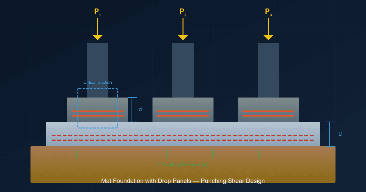
Mat foundations (also called raft foundations) distribute heavy column loads over a large area, making them ideal for structures on weak or variable soil. When punching shear at columns exceeds the slab capacity, drop panels provide the additional depth exactly where it's needed — without increasing the entire mat thickness.
This guide covers the complete design workflow for mat foundations with drop panels, including worked examples and code provisions, for design by hand.
What Is a Mat Foundation with Drop Panels?
A mat foundation is a thick reinforced concrete slab that supports all columns and walls of a structure. Unlike isolated footings, a mat acts as a continuous raft that:
- Distributes loads uniformly to the soil
- Reduces differential settlement
- Bridges over weak pockets in the subgrade
- Resists uplift and hydrostatic pressure
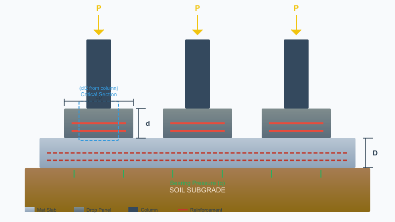
A drop panel is a localised thickening of the slab below the column. It increases the effective depth d at the critical section, which:
- Enlarges the punching shear perimeter
- Increases the shear area
b₀ × d - Reduces the nominal shear stress
τᵥ
Drop panels are more economical than increasing the entire mat depth when only a few heavily loaded columns fail the punching check.
When to Use Drop Panels
Consider drop panels when:
| Condition | Recommendation |
|---|---|
| Punching shear fails at isolated columns | Add drop panel at those columns |
| Column loads vary significantly | Drop panels under heavy columns only |
| Mat depth > 600 mm without drops | Evaluate cost: drops may save concrete |
| Edge or corner columns | Drops help where perimeter is reduced |
The bearing capacity module helps you determine the allowable soil pressure, which sets the mat plan area before punching checks begin.
Design Procedure: Step by Step
Step 1: Preliminary Mat Sizing
- Calculate total structural load:
ΣP = ΣDL + ΣLL(unfactored) - Determine net safe bearing capacity from geotechnical investigation
- Required mat area:
A = ΣP / q_net - Choose plan dimensions to cover all columns with adequate edge distances
Step 2: Establish Mat Depth
The mat depth D is governed by:
- One-way shear at face of column strips
- Punching shear at d/2 from column faces
- Flexural depth for bending moments
A first estimate: D = L/10 where L is the longest span between columns, then verify.
Step 3: Punching Shear Check
For each column, check:
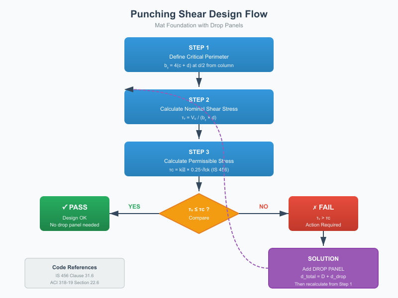
τᵥ = Vᵤ / (b₀ × d)

where:
  Vᵤ = Factored column load − soil reaction within critical perimeter
  b₀ = Critical perimeter at d/2 from column face
  d  = Effective depth of slab (or slab + drop)
IS 456 Clause 31.6.3 gives the permissible stress:
τc = kₛ × 0.25 × √fck

where kₛ = 0.5 + βc ≤ 1.0
      βc = short side / long side of column
ACI 318-19 Section 22.6.5 uses the minimum of three equations, accounting for aspect ratio, perimeter size, and column location.
If τᵥ > τc, the check fails and you need either:
- A deeper mat throughout, or
- A drop panel at that column
Drop Panel Design
Sizing the Drop Panel
Per IS 456 Clause 31.4.2 and ACI 318-19 Section 8.2.4:
| Parameter | IS 456 | ACI 318 |
|---|---|---|
| Minimum width | ≥ column width + 2d | ≥ L/6 each side |
| Minimum projection | ≥ L/6 from column face | ≥ L/6 from column face |
| Minimum depth | ≥ D/4 of slab | ≥ D/4 of slab |
Where L is the span in each direction. A practical guideline:
- Drop panel width: 1.5h to 2h (h = column dimension)
- Drop panel depth: 100–200 mm beyond the mat soffit
Recalculating Punching Shear
With a drop panel of depth d_drop:
- New effective depth at column:
d_total = D + d_drop − cover - Critical perimeter shifts to d_total/2 from column face
- Recalculate
τᵥand compare withτc
Worked Example: Interior Column
Given:
- Column size: 450 × 450 mm
- Factored load: 2400 kN
- Mat depth: 500 mm, cover = 50 mm → d = 450 mm
- Concrete grade: M30 (fck = 30 MPa)
- Net soil pressure: 150 kPa
Step 1: Critical perimeter
b₀ = 4 × (450 + 450) = 3600 mm
Step 2: Shear force
Area within b₀ = (450 + 450)² = 810,000 mm² = 0.81 m²
Soil reaction = 0.81 × 150 = 121.5 kN
Vᵤ = 2400 − 121.5 = 2278.5 kN
Step 3: Applied shear stress
τᵥ = 2278.5 × 1000 / (3600 × 450)
   = 1.406 N/mm²
Step 4: Permissible stress (IS 456)
βc = 450/450 = 1.0
kₛ = 0.5 + 1.0 = 1.5 → capped at 1.0
τc = 1.0 × 0.25 × √30 = 1.37 N/mm²
Result: τᵥ (1.41) > τc (1.37) — Fails
Solution: Add drop panel
Try 150 mm drop → d_total = 600 mm:
b₀ = 4 × (450 + 600) = 4200 mm
Area = 1.1025 m² → reaction = 165 kN
Vᵤ = 2400 − 165 = 2235 kN
τᵥ = 2235 × 1000 / (4200 × 600) = 0.887 N/mm²
Check: 0.89 < 1.37 — Passes ✓
Reinforcement Detailing
Mat Reinforcement
- Bottom steel: Resists hogging moments between columns
- Top steel: Resists sagging moments over columns
- Minimum steel per IS 456: 0.12% for Fe 500, 0.15% for Fe 415
Use the rebar development length calculator to verify anchorage.
Drop Panel Reinforcement
- Extend column reinforcement through the drop
- Provide additional bars at drop panel edges for local bending
- Lap length per IS 456 lap length provisions
Inputs from CivilTech Studio
CivilTech Studio does not design mat foundations. It gives the inputs for a hand design: factored column loads from load combinations, and the soil's bearing capacity from the bearing capacity calculator and the soil investigation module.
Key Design Checks Summary
| Check | Location | Code Reference |
|---|---|---|
| Punching shear | d/2 from column | IS 456 Cl. 31.6, ACI 318 Sec. 22.6 |
| One-way shear | d from column face | IS 456 Cl. 40.1, ACI 318 Sec. 22.5 |
| Flexure | Max moment sections | IS 456 Annex G, ACI 318 Sec. 22.2 |
| Development | Bar termination | IS 456 Cl. 26.2, ACI 318 Sec. 25.4 |
Common Mistakes to Avoid
- Using gross SBC instead of net SBC for mat sizing
- Ignoring soil reaction within the critical perimeter when computing Vᵤ
- Undersizing drop panels — they must be wide enough to capture the new critical section
- Forgetting unbalanced moment at edge columns (use ACI 318 Sec. 8.4.4.2)
- Inadequate anchorage of column bars into the mat
Related Resources
- Isolated Footing Design Calculator — single column footings
- Combined Footing Design — two to six columns in a line on one base
- Retaining Wall Design — lateral earth pressure and stability
- Concrete Mix Design — specify the right M30 or M35 mix
- Section Design Calculator — verify flexural capacity of any section
FAQ
What is a mat foundation with drop panels?
A mat foundation is a thick concrete slab supporting all columns and walls. Drop panels are localised thickenings beneath heavily loaded columns that increase the effective depth at the critical punching shear perimeter, reducing the shear stress without increasing the entire mat depth.
How do you size a drop panel for punching shear?
The drop panel width should be at least 1.5 to 2 times the column dimension (or L/6 per ACI 318), and its depth at least D/4 of the slab thickness. After adding the drop, recalculate the critical perimeter at (d + d_drop)/2 from the column face and verify τᵥ ≤ τc.
What is the critical perimeter in punching shear?
The critical perimeter b₀ is located at a distance d/2 from the column face, where d is the effective slab depth. For a square column of side c with effective depth d: b₀ = 4 × (c + d). The punching shear stress τᵥ = Vᵤ / (b₀ × d).
When should I use drop panels versus increasing mat thickness?
Use drop panels when only a few columns fail punching shear and the rest of the mat is adequate. Drop panels are more economical than increasing the entire mat depth when column loads vary significantly across the building.
What codes govern mat foundation design?
IS 456:2000 Clause 31.6 and IS 2950 for Indian practice; ACI 318-19 Section 22.6 for American practice; Eurocode 2 (EN 1992-1-1) Section 6.4 for European practice. All codes require checking punching shear at a critical section d/2 from the column face.
Educational reference. Always verify against the governing code and your project specification.