#is-456#footing-design#isolated-footing#foundation-design#rcc-design#punching-shear
Isolated Footing Design (IS 456) — Worked Example
Isolated footing design IS 456 guide, step by step: plan size from net SBC, depth from one-way shear, punching and dowel anchorage, steel by Annex G. A full worked example for a 900 kN column, hand-checked against the CivilTech Studio engine.
Updated 4 Nov 202621 min read
 Try it free: open this worked example in Foundation DesignOpen →
On this page
- What governs an isolated footing design
- Step-by-step isolated footing design procedure (IS 456)
- Worked example: isolated footing design to IS 456
- IS 456 clause reference for isolated footings
- IS 456 vs ACI 318 vs Eurocode 2 for pad footings
- Common mistakes in isolated footing design
- How CivilTech Studio does this
- Frequently asked questions
Isolated Footing Design to IS 456: Step-by-Step Procedure with a Worked Example
By the CivilTech Studio Engineering Team
To design an isolated footing to IS 456, you size the plan from the service load and the soil's safe net bearing capacity (SBC). You then size the depth and steel from the factored load, using the net upward pressure. Five things govern the result: soil bearing, the bending moment at the column face (cl. 34.2.3.2), one-way shear at a distance d from the face (cl. 34.2.4.1(a)), punching shear on a perimeter at d/2 (cl. 34.2.4.1(b) with 31.6), and the anchorage of both the bottom bars and the column's starter bars. In many pad footings under ordinary building columns, bearing sets the plan, and one-way shear or dowel anchorage sets the depth. Punching governs less often than many people expect, mainly on small, heavily loaded footings.
This guide works through every step with the formulas. It then runs one footing, a 400 × 400 mm column carrying 600 kN dead and 300 kN imposed load, through the IS 456 foundation design calculator and checks each number by hand.
What governs an isolated footing design
An isolated (pad) footing is a two-way cantilever. Soil pressure pushes up, the column pushes down, and the slab bends and shears around the column. IS 456 Section 34 sets out where to check it:
| Check | Load level | Critical section | IS 456 clause |
|---|---|---|---|
| Soil bearing | Service (unfactored) | Whole base | 34.1.1 (with the soil report) |
| Bending | Factored | Face of column | 34.2.3.2 |
| One-way shear | Factored | At d from column face | 34.2.4.1(a), Table 19 |
| Two-way (punching) shear | Factored | Perimeter at d/2 from column faces | 34.2.4.1(b), 31.6.3.1 |
| Bar anchorage | Factored | Past the column face | 34.2.4.3, 26.2.1 |
| Load transfer at column base | Factored | Column–footing interface | 34.4 |
| Minimum steel, spacing | — | Each direction | 34.5.1, 26.5.2.1, 26.3.3 |
| Edge thickness | — | Footing edge | 34.1.2 (≥ 150 mm on soil) |
Two points trip people up.
- Bearing is a service check, and the concrete design is a factored check. You do not compare 1.5(D + L) with the SBC, and you do not design bars for the working load.
- Self-weight does not bend a uniformly supported footing. The footing and the backfill above it press down exactly where the soil they add pushes up. They count for bearing, but the concrete is designed for the net upward pressure, which is the column load divided by the area.
Step-by-step isolated footing design procedure (IS 456)
Step 1: Plan area from net safe bearing capacity
A soil report gives the safe net bearing capacity: the pressure the soil can take above the overburden it already carried before excavation. To check it honestly, add everything that sits on the soil and subtract the soil that was dug out:
q_net = (P + W_footing + W_backfill) / (B × L) − γ_soil × Df ≤ SBC_net
Here P is the service column load (D + L), Df is the founding depth and γ_soil is the unit weight of the soil. With concrete at 25 kN/m³ and soil at 18 kN/m³, everything after P/A reduces to (25 − 18) × D, with D the footing depth in metres. That is only about 4 kPa for a 550 mm footing, because concrete is a little heavier than the soil it replaces.
The familiar shortcut A = 1.1 P / SBC adds 10 % for self-weight. That is reasonable against a gross SBC, but it over-sizes footings when the SBC is net. The worked example below shows by how much.
For a column with moments, the pressure is no longer uniform:
q_max, q_min = P/A × (1 ± 6e_x/L ± 6e_y/B), e = M / P
This holds only while the resultant stays in the kern (e ≤ L/6 in one direction). Beyond that, part of the base lifts off and the pressure has to be solved as a no-tension distribution. Use your bearing capacity calculation for the SBC itself. The footing design only consumes it.
Step 2: Net upward factored pressure
q_u = P_u / (B × L), P_u = 1.5 (D + L) (IS 456 Table 18)
Under wind or earthquake, Table 18 also gives 1.2(D + L ± W/E) and 1.5(D ± W/E), and 0.9D ± 1.5W/E where the dead load helps stability. Our load combinations tool lists them in full.
Step 3: Bending moment at the face of the column
For a square column of side c on a square footing of side B, the cantilever projection is a = (B − c)/2:
M_u = q_u × B × a² / 2
IS 456 cl. 34.2.3.2 takes this at the face of a concrete column. Under a masonry wall, the section is halfway between the centre and the edge of the wall.
Step 4: Effective depth and steel (Annex G)
The two layers of bottom bars sit at different depths:
d_lower = D − cover − φ/2
d_upper = D − cover − φ − φ/2
Use the upper layer's d for the direction whose bars sit on top. The steel comes from IS 456 Annex G:
M_u = 0.87 f_y A_st d (1 − A_st f_y / (b d f_ck))
Check it against the minimum of 0.12 % of b × D for HYSD bars (cl. 26.5.2.1, referred to by 34.5.1) and the maximum spacing of 3d or 300 mm (cl. 26.3.3(b)). For a rectangular footing, the short-direction bars are concentrated in a central band equal in width to the short side (cl. 34.3.1(c)):
bars in central band = total short-direction bars × 2 / (β + 1), β = L / B
Step 5: One-way shear at d from the column face
V_u = q_u × B × (a − d)
τ_v = V_u / (B × d)  ≤  τ_c   (Table 19, from p_t = 100 A_st / (B d) and f_ck)
Footings carry no shear reinforcement in practice, so if τ_v exceeds τ_c you make the footing deeper or add flexural steel to raise p_t.
Step 6: Punching (two-way) shear at d/2
The critical perimeter sits at d/2 from every column face (cl. 31.6.1, applied to footings by 34.2.4.1(b)):
b0 = 2 × [(c1 + d) + (c2 + d)]
V_u = P_u − q_u × (c1 + d)(c2 + d)
τ_v = V_u / (b0 × d)  ≤  k_s × 0.25 √f_ck,    k_s = 0.5 + β_c ≤ 1,   β_c = short side / long side of column
When the column carries a moment, part of it is transferred by shear on this perimeter, which raises τ_v on one side (cl. 31.6.2.2). If the column sits near the edge of the footing, the side of the perimeter that would fall off the footing is dropped.
Step 7: Development length past the critical section
L_d = φ σ_s / (4 τ_bd), σ_s = 0.87 f_y, τ_bd = 1.4 × 1.6 = 2.24 MPa for M25 deformed bars (cl. 26.2.1)
The available length is the projection from the column face minus the end cover. If that is short, a 90° bend adds 8φ of anchorage value (cl. 26.2.2.1).
Step 8: Load transfer at the column base
The bearing stress where the column meets the footing is limited to 0.45 f_ck × √(A2/A1), with the root capped at 2 (cl. 34.4). Starter bars (dowels) of at least 0.5 % of the column area, and at least four of them (cl. 34.4.3), carry any excess. They must be anchored in compression inside the footing. That length, D − cover − two bar layers, quietly sets the minimum depth of many small footings.
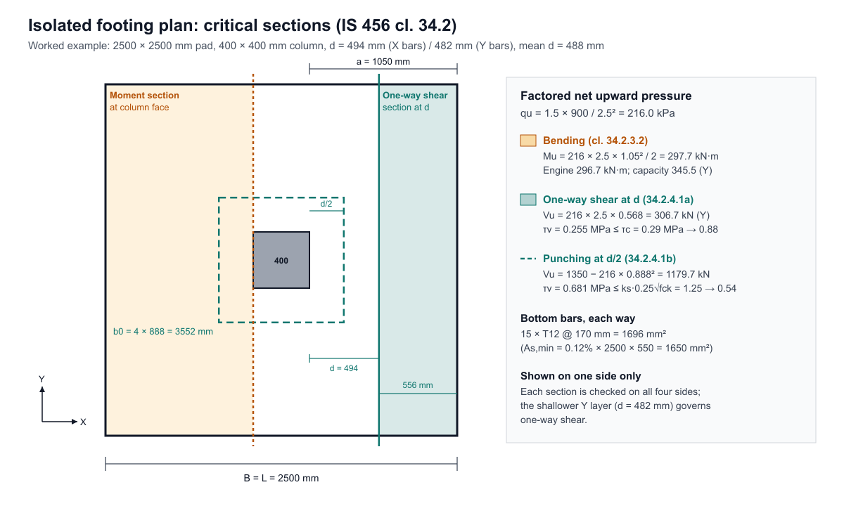
Worked example: isolated footing design to IS 456
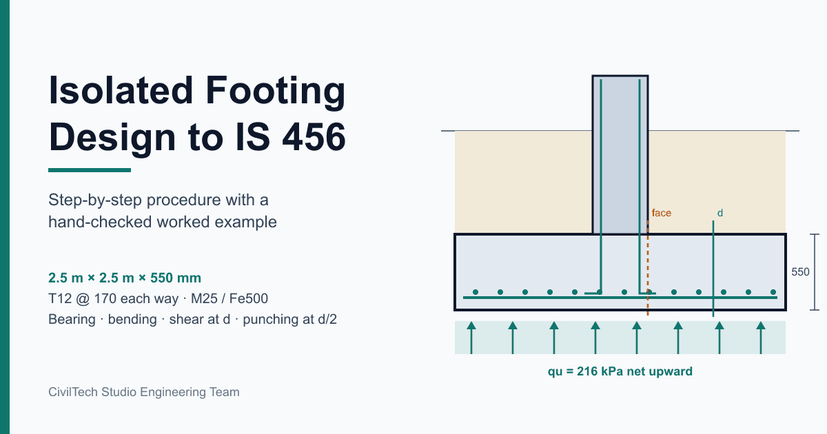
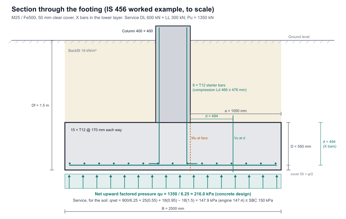
Data. Column 400 × 400 mm. Service loads: dead 600 kN, imposed 300 kN, axial only. M25 concrete, Fe500 bars, 50 mm clear cover (cl. 26.4.2.2). Safe net SBC 150 kPa at a founding depth of 1.5 m. Soil 18 kN/m³, concrete 25 kN/m³.
We ran this case through the CivilTech Studio engine, the same function the foundation design module calls, in design mode, flat pad. The script and its full output are published with this article (worked_example.py and worked_example.txt).
Engine result
| Item | Result |
|---|---|
| Plan | 2500 × 2500 mm |
| Depth D | 550 mm |
| Bottom bars, each way | 15 × T12 @ 170 mm (1696 mm²) |
| Starter bars | 8 × T12 |
| Lap length (bottom bars) | 583 mm |
| Concrete / steel | 3.44 m³ / 71.5 kg (including starter bars) |
| Cost at default rates | ₹33,226 (excavation, PCC, formwork and backfill included) |
| Governing check | Soil bearing, ratio 0.983 under D + L |
Every check the engine ran:
| Check | Demand | Capacity | Ratio | Combination | Clause |
|---|---|---|---|---|---|
| Soil bearing (net) | 147.4 kPa | 150.0 kPa | 0.983 | D + L | 34.1.1 |
| Bending, bars along X (d = 494) | 296.7 kN·m | 354.4 kN·m | 0.837 | 1.5(D + L) | 34.2.3.2, Annex G |
| Bending, bars along Y (d = 482) | 296.7 kN·m | 345.5 kN·m | 0.859 | 1.5(D + L) | 34.2.3.2, Annex G |
| One-way shear, X | 299.2 kN | 358.1 kN | 0.836 | 1.5(D + L) | 34.2.4.1(a), Table 19 |
| One-way shear, Y | 305.7 kN | 349.4 kN | 0.875 | 1.5(D + L) | 34.2.4.1(a), Table 19 |
| Punching shear | 0.678 MPa | 1.250 MPa | 0.543 | 1.5(D + L) | 34.2.4.1(b), 31.6.3 |
| Column base bearing | 1350 kN | 2103 kN | 0.642 | 1.5(D + L) | 34.4 |
| Starter bar area | 800 mm² | 905 mm² | 0.884 | — | 34.4.3 |
| Starter bar anchorage (compression) | 466 mm | 476 mm | 0.979 | 1.5(D + L) | 26.2.1 |
| Minimum steel, each way | 1650 mm² | 1696 mm² | 0.973 | — | 26.5.2.1 |
| Anchorage past face, Y bars | 500 mm | 1000 mm | 0.500 | 1.5(D + L) | 34.2.4.3, 26.2.1 |
| Bar spacing | 170 mm | 300 mm | 0.567 | — | 26.3.3(b) |
| Edge thickness | 150 mm | 550 mm | 0.273 | — | 34.1.2 |
| Crack width, Y bars | 0.025 mm | 0.30 mm | 0.084 | D + L | 35.3.2, Annex F |
Stability (overturning and sliding to cl. 20) produces no checks here, because the column carries no moment or horizontal force.
Hand check of the key numbers
1. Plan area. For D = 550 mm, the footing adds 25 × 0.55 = 13.75 kPa and the backfill 18 × (1.5 − 0.55) = 17.10 kPa. The excavated soil removes 18 × 1.5 = 27.0 kPa.
q_net = P/A + 13.75 + 17.10 − 27.0 = P/A + 3.85 kPa
A_req = 900 / (150 − 3.85) = 6.16 m²  →  √6.16 = 2.48 m  →  adopt 2.5 m × 2.5 m
q_net = 900 / 6.25 + 3.85 = 144.0 + 3.85 = 147.85 kPa
The engine reports 147.4 kPa. It leaves out the backfill over the 0.16 m² footprint of the column: 0.16 × 17.1 / 6.25 = 0.44 kPa. The shortcut 1.1P/SBC = 6.6 m² would have produced a 2.6 m footing, 8 % more area than the net-pressure calculation needs.
2. Net upward factored pressure.
P_u = 1.5 × 900 = 1350 kN
q_u = 1350 / 6.25 = 216.0 kPa
3. Moment at the column face.
a   = (2500 − 400) / 2 = 1050 mm
M_u = 216.0 × 2.5 × 1.05² / 2 = 297.7 kN·m
The engine gives 296.7 kN·m, 0.3 % lower. It integrates the net pressure cell by cell. Over the column's footprint there is no backfill, so the net upward pressure is higher there and slightly lower everywhere else: 215.3 kPa. 215.3 × 2.5 × 1.05² / 2 = 296.7 kN·m, which matches exactly.
4. Steel. X bars sit in the lower layer, so d_x = 550 − 50 − 6 = 494 mm and d_y = 494 − 12 = 482 mm. Solving Annex G for the Y direction:
296.7 × 10⁶ = 0.87 × 500 × A_st × 482 × (1 − A_st × 500 / (2500 × 482 × 25))
A_st,req ≈ 1450 mm²   (X direction: ≈ 1413 mm²)
A_st,min = 0.12 % × 2500 × 550 = 1650 mm²   ← governs
15 × T12 = 15 × 113.1 = 1696 mm²
spacing  = (2500 − 2 × 50 − 12) / 14 = 170.6  →  170 mm
Minimum steel governs the bars, as it often does with Fe500 and a footing deep enough for shear. The engine's capacity check, 0.87 × 500 × 1696 × (482 − 0.42 × 32.8) = 345.5 kN·m, agrees with its reported value.
5. One-way shear (Y, the shallower layer).
a − d = 1050 − 482 = 568 mm
V_u   = 216.0 × 2.5 × 0.568 = 306.7 kN      (engine 305.7, the same 215.3 kPa effect)
τ_v   = 306.7 × 10³ / (2500 × 482) = 0.255 MPa
p_t   = 1696 / (2500 × 482) = 0.141 %  →  τ_c = 0.29 MPa (Table 19, M25, p_t ≤ 0.15)
ratio = 0.255 / 0.29 = 0.88
6. Punching shear. Use the mean d = (494 + 482)/2 = 488 mm:
b0    = 4 × (400 + 488) = 3552 mm
V_u   = 1350 − 216.0 × 0.888² = 1350 − 170.3 = 1179.7 kN    (engine 1175.8)
τ_v   = 1179.7 × 10³ / (3552 × 488) = 0.681 MPa
k_s   = 0.5 + 1.0 = 1.5 → 1.0;   τ_c = 0.25 × √25 = 1.25 MPa
ratio = 0.681 / 1.25 = 0.54
7. Development length of the bottom bars.
L_d = 12 × 0.87 × 500 / (4 × 2.24) = 583 mm  (48.5φ)
available = 1050 − 50 = 1000 mm  → straight bars are fine
The engine reports 500 mm because it scales the bar stress by the ratio of required to provided capacity (0.86 in Y). IS 456 cl. 26.2.1 permits this, but quoting the full-stress 583 mm is the conservative habit. The engine's 583 mm lap length is the full-stress value.
8. Starter bars and column base.
Bearing on column concrete: 0.45 × 25 × 400 × 400 = 1800 kN ≥ 1350 kN
Minimum dowels: 0.5 % × 160 000 = 800 mm²  →  8 × T12 = 905 mm²
Compression L_d (τ_bd + 25 %): 12 × 435 / (4 × 2.80) = 466 mm
Available: 550 − 50 − 12 − 12 = 476 mm  → ratio 0.98
Hand calculation and engine agree to within 0.5 % on every force, moment and stress. The small gaps all come from the engine leaving out backfill over the column footprint. They are not a different method. The one larger difference, the bottom bars' development length (583 mm by hand, 500 mm in the engine), is the stress-ratio reduction explained in item 7.
Why 550 mm and not 500 mm?
We checked the same 2.5 m footing at D = 500 mm in the engine's check mode:
- With T12 at 170 mm, one-way shear fails at a ratio of 1.04.
- Eight T12 starter bars need 466 mm of compression anchorage but get only 426 mm, a ratio of 1.09.
Punching is nowhere near critical at either depth. Closer bars help shear, but the dowel anchorage cannot be fixed without smaller bars than the module offers (T12 is its smallest starter bar). So the depth here comes from dowel anchorage and one-way shear, not punching. If you remember one thing from this example, make it that: check the starter-bar length before you shave the depth.
IS 456 clause reference for isolated footings
| Topic | Clause | What it says (summary) |
|---|---|---|
| Load factors | Table 18 | 1.5(D + L); 1.2(D + L ± W/E); 1.5(D ± W/E); 0.9D ± 1.5W/E |
| Stability | 20.1, 20.2 | Overturning: 0.9 × restoring dead ≥ 1.2 dead + 1.4 imposed overturning. Sliding: FOS 1.4 |
| Two-way shear strength | 31.6.3.1 | τ_c = k_s × 0.25√f_ck, k_s = 0.5 + β_c ≤ 1 |
| Moment transfer by shear | 31.6.2.2 | Part of an unbalanced moment raises τ_v on the perimeter |
| Edge thickness | 34.1.2 | At least 150 mm for footings on soil |
| Plain footing spread | 34.1.3 | Projection limited by tan α against q₀ and f_ck |
| Moment section | 34.2.3.2 | Face of column (halfway to the edge of a masonry wall) |
| Shear sections | 34.2.4.1 | One-way at d, two-way at d/2 from the column face |
| Anchorage section | 34.2.4.3 | The same planes as for bending |
| Central band | 34.3.1(c) | 2/(β + 1) of the short bars in a band equal to the short side |
| Column base transfer | 34.4, 34.4.3 | 0.45 f_ck √(A2/A1) ≤ 2 × 0.45 f_ck; dowels ≥ 0.5 % of the column, at least 4 bars |
| Nominal top steel | 34.5.2 | Where D > 1 m, 360 mm²/m each way on each face |
| Development length | 26.2.1 | L_d = φσ_s / 4τ_bd |
| Cover | 26.4.2.2 | 50 mm minimum for footings |
| Crack width | 35.3.2, Annex F | 0.3 mm generally; 0.2 mm suggested where in contact with soil |
IS 456 vs ACI 318 vs Eurocode 2 for pad footings
The module designs the same pad to all three codes, and also to AS 3600 and CSA A23.3. Here is how the three most-used codes differ in what the engine actually applies:
| Item | IS 456:2000 | ACI 318-19 | EN 1992-1-1 (EC2) |
|---|---|---|---|
| Strength combination (D + L) | 1.5D + 1.5L | 1.4D; 1.2D + 1.6L | 1.35G + 1.5Q (EN 1990 6.10) |
| Soil (service) combination | D + L | D + L (ASCE 7 2.4.1) | G + Q characteristic |
| Flexure | 0.87f_y A_s (d − 0.42x_u), x_u ≤ x_u,max | φA_s f_y (d − a/2), φ 0.9, ε_t ≥ 0.004 | A_s f_yd (d − 0.4x), x ≤ 0.45d |
| One-way shear section | d from face | d from face | d from face |
| One-way shear strength | τ_c from Table 19 | φ0.66ρ^(1/3)√f'c ≤ φ0.42√f'c, φ 0.75, no size effect (13.2.6.2) | 0.12k(100ρf_ck)^(1/3) ≥ v_min |
| Punching perimeter | d/2, rectangular | d/2, rectangular | Rounded control perimeters from 0.25d to 2d (6.4.4(2)) |
| Punching strength | k_s × 0.25√f_ck | φ × min(0.33, 0.17(1 + 2/β), 0.083(2 + α_s d/b0))√f'c | v_Rd,c × 2d/a, plus 0.4νf_cd at the column face |
| Minimum steel | 0.12 % b × D (HYSD) | 0.0018 A_g | max(0.26f_ctm/f_yk, 0.0013) b × d |
| Central band, rectangular footing | Yes, 34.3.1(c) | Yes, 13.3.3.3 | No band rule |
| Column base bearing | 0.45f_ck√(A2/A1), root ≤ 2 | φ0.85f'c√(A2/A1), φ 0.65, root ≤ 2 | f_cd√(A_c1/A_c0) ≤ 3f_cd |
| Cover against ground | 50 mm | 75 mm | 40 mm on blinding, 75 mm against soil |
| Overturning | 0.9D restoring vs 1.2D + 1.4Q | ASD, FOS 1.5 (1.0 with 0.6D) | EQU: 0.9G stabilising vs 1.1G + 1.5Q |
EC2's punching check differs most. It searches several control perimeters out to 2d and lets the soil pressure inside each one reduce the shear. IS 456 and ACI check a single perimeter at d/2. That is why an EC2 pad and an IS 456 pad under the same load rarely come out the same depth.
Common mistakes in isolated footing design
- Using factored load for bearing. Bearing is checked at service load against the SBC. Use P_u only for the concrete.
- Treating a net SBC as gross, or the reverse. Adding 10 % to P and also using a net SBC double-counts. Read the soil report and use the matching formula.
- Designing the bars for the gross pressure. The footing's own weight and the backfill do not bend it. Design for q_u = P_u / A.
- Using one d for both directions. The upper layer has a d that is one bar diameter smaller. In the example, Y shear (d = 482) is the more critical direction.
- Checking only punching. For lightly reinforced pads, one-way shear at d often governs first. Table 19's τ_c at p_t ≈ 0.15 % is only 0.29 MPa for M25.
- Forgetting the dowels. Starter bars need compression anchorage inside the footing. A T16 dowel in M25 with Fe500 needs about 621 mm. A footing designed only for shear may not have that depth.
- Spacing short bars uniformly in a rectangular footing. IS 456 34.3.1(c) asks for the central band. Uniform spacing under-reinforces the zone under the column.
- Ignoring moments in the bearing check. An eccentricity of L/10 raises the edge pressure 60 % above the mean. Once e > L/6, part of the base lifts off and P/A ± M/Z no longer applies.
How CivilTech Studio does this
The isolated footing design module runs the procedure above as a search, not a single pass:
- Inputs. Dead, imposed, snow, wind and earthquake cases, each with P, Mx, My, Hx and Hy. Column size and offset. f_ck, f_y and cover. SBC (net or gross), founding depth, soil unit weight, water table, base friction and optional passive resistance.
- Combinations generated per code. For IS 456: Table 18 strength combinations, IS 875-5 / IS 1893 service combinations, and cl. 20 stability with 0.9D restoring. The dead-alone combination is included, because the imposed load can hold down a base that moments would otherwise lift. Wind is applied in both senses, and earthquake in two directions is combined 100/30. You can exclude generated combinations or add your own.
- Contact pressure. A tensionless, biaxial pressure plane. Partial lift-off under large moments is solved, not approximated, and full contact is checked under sustained loads.
- Checks reported one by one. Every check is shown as demand ÷ capacity, with its combination, its clause and its working. That covers bearing, overturning, sliding, uplift, bending, one-way shear, punching (including moment transfer and perimeters cut at a free edge), column-base bearing, dowel area and anchorage, minimum steel, spacing, central band, edge thickness and crack width.
- Design search. Plan shapes up to the aspect limit you set. For each, the least passing depth and the lightest bars. Pad against sloped is decided on total cost (concrete, steel, formwork, excavation, PCC, backfill), at rates you can edit. Every passing option is listed with its own utilisation, so you can pick a squarer or shallower one.
- Check mode. Enter an existing footing and its bars to see exactly what passes and what fails.
- Outputs. A bar bending schedule, quantities, a 3D view, shear and moment strip diagrams for each strength combination, and a calculation PDF containing every check's working. An optional FEM cross-check analyses the footing as a plate on tensionless springs. It is shown for comparison and never changes the rigid-method result.
- Other footing types. Strip, plain concrete, sloped, combined footings and mats (2–6 columns), and pile caps (1–9 piles) use the same checking approach. Strap and raft footings go to the module's IntelliCascade engine (patent-pending).
After design, carry the bar schedule into the BBS and cutting length calculator, or check anchorage of other members with the development length calculator.
Frequently asked questions
How do you calculate the size of an isolated footing as per IS 456?
Divide the service load (D + L) by the safe net bearing capacity minus the small extra pressure from the footing and backfill. With 25 kN/m³ concrete and 18 kN/m³ soil, that extra is (25 − 18) × D, about 7 kPa per metre of footing depth. Round the side up to the nearest 50 or 100 mm. If the SBC is gross, the common 1.1P/SBC approximation is reasonable.
What is the minimum depth of an isolated footing in IS 456?
IS 456 cl. 34.1.2 requires at least 150 mm at the edge of a footing on soil. In practice, one-way shear, punching shear and the compression anchorage of the starter bars set the depth, often 450–700 mm for ordinary building columns.
Where is the critical section for shear in a footing?
For one-way shear, at a distance d from the face of the column. For punching (two-way) shear, on a perimeter at d/2 from all column faces (IS 456 cl. 34.2.4.1).
Why does one-way shear sometimes govern over punching?
Punching strength (k_s × 0.25√f_ck, which is 1.25 MPa for M25) is much higher than one-way shear strength at low steel ratios (0.29 MPa for M25 at p_t ≈ 0.15 %). A wide footing with minimum steel can therefore fail one-way shear first, as the worked example shows at D = 500 mm.
What is the minimum reinforcement in a footing as per IS 456?
0.12 % of the gross section (b × D) for HYSD bars and 0.15 % for mild steel, in each direction (cl. 34.5.1 referring to 26.5.2.1). The maximum spacing is 3d or 300 mm, whichever is less.
Do you include the footing's self-weight in the design?
Yes for bearing, no for bending and shear. The footing's weight and the backfill are supported directly by the soil beneath them. They add to the pressure on the soil, but they do not bend the slab, so the concrete is designed for the net upward pressure P_u / A.
How is a rectangular isolated footing reinforced differently from a square one?
The long bars are spaced uniformly. Of the short bars, the fraction 2/(β + 1) is placed in a central band equal in width to the short side, where β is the ratio of the long side to the short side (IS 456 cl. 34.3.1(c)). The remainder is spread over the two outer strips.
Is a sloped footing cheaper than a flat pad?
Sometimes. A slope saves concrete at the edges but needs top formwork once it is steeper than about 30°, and more careful casting. The CivilTech Studio design search costs both and picks the cheaper one, including excavation and backfill, rather than assuming either.
Run your own column through the IS 456 isolated footing calculator, change the SBC or the steel grade, and watch which check takes over.
Educational reference. Always verify against the governing code and your project specification.