#geotechnical#spt#bearing-capacity#is-6403#liquefaction#foundation-design
SBC from SPT N Value (IS 6403) — Worked Example
How to find safe bearing capacity from SPT N value: N corrections, the IS 6403 shear check, Meyerhof, Bowles and Burland & Burbidge settlement methods, water table effects and IS 1893 liquefaction screening, with a full worked example.
Updated 4 Nov 202620 min read
 Try it free: run this design in Geotechnical AnalysisOpen →
On this page
- SBC vs safe bearing pressure vs ultimate bearing capacity
- SPT N value corrections
- SBC methods, as the module implements them
- Settlement-governed vs shear-governed SBC
- Water table effect on bearing capacity
- Step-by-step: how to calculate SBC from SPT N values
- Worked example: alluvial borehole, B = 2.0 m, Df = 1.5 m
- Comparing methods: why the SBC values scatter
- Codes and references used
- Liquefaction screening from SPT (IS 1893)
- Common mistakes in SBC calculation from SPT
- How CivilTech Studio does this
- FAQ
Safe Bearing Capacity from SPT N Value: IS 6403 Method with Worked Example
By the CivilTech Studio Engineering Team
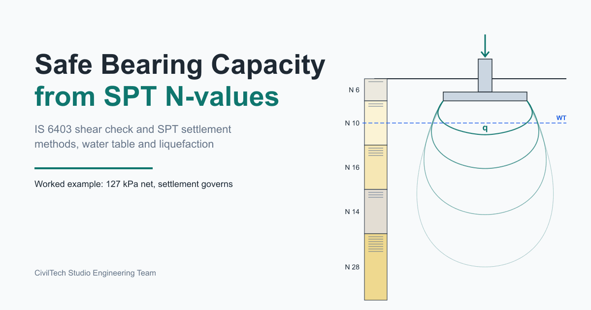
To get the safe bearing capacity from an SPT N value, you correct the field N, work out the net pressure the soil can carry without shear failure (the ultimate value divided by a factor of safety, per IS 6403), work out the net pressure that keeps settlement within a limit (usually 25 mm for footings on sand), and adopt the lower of the two. That lower value is the allowable bearing pressure, though many soil reports still call it "SBC". It is normally quoted net, meaning the pressure above the existing overburden at founding level. The gross value adds back γ·Df. On loose to medium sands with footings wider than about 1.5 m, settlement usually governs, not shear. The worked example below shows this: the shear-based SBC is 223 kPa, but 25 mm of settlement limits the footing to 127 kPa.
This guide walks through every step the way the CivilTech Studio geotechnical analysis module does it, using a real engine run on a typical Indo-Gangetic alluvial borehole.
SBC vs safe bearing pressure vs ultimate bearing capacity
These terms get mixed up in soil reports all the time, and the mix-ups can be expensive:
| Term | What it means | Governs |
|---|---|---|
| Net ultimate bearing capacity, q_nu | Net pressure that causes shear failure of the soil | Collapse |
| Net safe bearing capacity (SBC) | q_nu ÷ factor of safety | Shear |
| Safe bearing pressure (SBP) | Net pressure that produces the permissible settlement | Settlement |
| Allowable bearing pressure | Lower of SBC and SBP. This is the design value. | Whichever is lower |
| Gross pressure | Net pressure + overburden γ·Df at founding level | Used only when the footing check uses gross loads |
A consultant who writes "SBC = 15 t/m²" in a report usually means the allowable (lower) value. Check whether it is net or gross, and whether settlement was checked. 1 t/m² = 9.81 kPa, so 15 t/m² is about 147 kPa.
SPT N value corrections
The field N (blows for the last 300 mm of 450 mm penetration, IS 2131) depends on the rig as well as the soil. Before it goes into any correlation it is corrected:
| Correction | Formula / value | Applied in the module |
|---|---|---|
| Hammer energy, CE | ER / 60 | 1.0 (assumes 60 % energy). Scale N yourself if your rig's ER is measured. |
| Borehole diameter, CB | 1.0 (≤ 115 mm), 1.05 (≤ 150 mm), 1.15 (> 150 mm) | 1.05 (150 mm hole) |
| Sampler, CS | 1.0 standard split spoon | 1.0 |
| Rod length, CR | 0.75 (< 3 m) to 1.0 (≥ 10 m) | Liquefaction screen only (IS 1893 Annex F / Youd et al. 2001 table) |
| Overburden, CN | √(100 / σ'v), with σ'v in kPa | Liao & Whitman, bounded 0.4 ≤ CN ≤ 1.7 |
| Dilatancy | N' = 15 + 0.5(N − 15) for N > 15 | Fine sand or silt below the water table (IS 2131) |
| Fines | (N1)60cs = α + β·(N1)60 | Liquefaction screen only (Youd et al. 2001) |
That gives two corrected values, and each method uses a specific one:
- N60 = N × CE × CB × CS. Corrected for energy and equipment, but not for overburden. Meyerhof, Bowles, Burland & Burbidge, and the clay correlations (cu and mv) are calibrated to N60.
- (N1)60 = N60 × CN. Normalised to 100 kPa effective stress. The friction angle used in the IS 6403 sand calculation comes from (N1)60.
Putting (N1)60 into Meyerhof's chart, or N60 into a φ correlation, is one of the most common errors in SBC calculations.
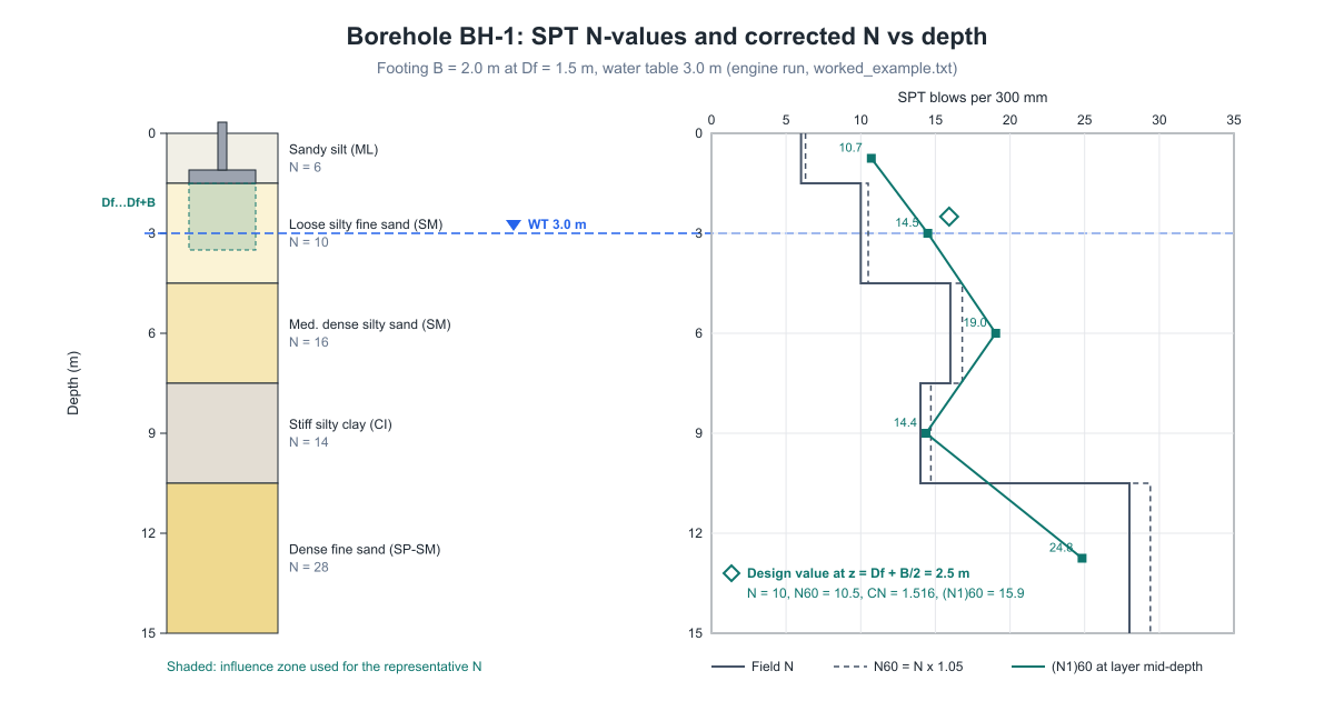
The module does not take one N per layer. It uses a representative N: the thickness-weighted average of field N over the zone from Df to Df + B below the footing. CN is evaluated at the middle of that zone, z = Df + B/2, using effective stress.
SBC methods, as the module implements them
IS 6403 (shear) for sand and silt
The friction angle comes from Peck, Hanson & Thornburn:
φ = 27.1 + 0.3·(N1)60 − 0.00054·(N1)60²      (sand/gravel, 26° to 45°)
φ = 25 + 0.2·(N1)60                          (silt, 25° to 35°)
The net ultimate capacity for a square footing under vertical load, per IS 6403 cl 5.1.2, is:
q_nu = q·(Nq − 1)·sq·dq + ½·B·γ·Nγ·sγ·dγ·W'
Nq = e^(π tanφ)·tan²(45° + φ/2),  Nγ = 2(Nq + 1)·tanφ
sq = 1.2, sγ = 0.8 (square);  dq = dγ = 1 + 0.1·(Df/B)·tan(45° + φ/2)
q = effective overburden at Df;  W' = water-table factor (see below)
Failure mode depends on φ. For φ ≥ 36° the module uses general shear. For φ ≤ 29° it uses local shear with φ' = tan⁻¹(0.67·tanφ). Between those limits it interpolates linearly. Net SBC = q_nu / 3.0. The factor of safety is fixed at 3.0 in this calculation. Indian reports use 2.5 to 3.0, so check which one your consultant used.
IS 6403 (shear) for clay
The clay case is an undrained (φ = 0) analysis. The undrained shear strength comes from Stroud (1974): cu = 4.5 × N60. Note that this uses N60, not (N1)60. Then q_nu = cu × 5.14 × 1.3 × dc, with dc = 1 + 0.2·(Df/B)·√Nφ.
Meyerhof (1956/1965) and Bowles (1977): settlement correlations for sand
Both give the net pressure for 25.4 mm of settlement directly from N60:
Meyerhof:  B ≤ 1.22 m  q = 11.98·N60·Fd
           B > 1.22 m  q = 7.99·N60·((3.28B + 1)/(3.28B))²·Fd
Bowles:    B ≤ 1.22 m  q = 19.16·N60·Fd
           B > 1.22 m  q = 11.98·N60·((3.28B + 1)/(3.28B))²·Fd
Fd = 1 + 0.33·Df/B ≤ 1.33;  then × S/25.4 and × Cw (water table)
In SI terms, the wide-footing Bowles expression is roughly N/0.08·((B + 0.3)/B)². Bowles is Meyerhof increased by about 50 %, because Meyerhof's original chart is known to be conservative. Neither correlation applies to clay or silt. For those soils the module reports the IS 6403 value in that row and labels it "n/a for clay/silt", so it is never mistaken for a Meyerhof value.
Burland & Burbidge (1985): settlement check
This check follows EN 1997-2 Annex F.3 for normally consolidated sand, with a square footing:
s = q'·B^0.7·Ic,   Ic = 1.71 / N̄^1.4
N̄ = mean N60 over z1 = B^0.763 below the base (2B if N falls with depth)
→ q_allow = s_allow / (B^0.7·Ic)
No separate water-table factor is applied, because N measured in situ already reflects the groundwater. For clay, the module replaces this check with 1-D consolidation, mv = 1/(450·N60) (Stroud & Butler), summed over 2B below the base with 2:1 stress spread.
Settlement-governed vs shear-governed SBC
The module computes every method and adopts the minimum net value as the allowable bearing pressure. It also reports which basis governs, shear or settlement. Some typical patterns:
- Narrow footings (B ≤ 1.2 m) on medium sand. Shear is more likely to govern, because the ½BγNγ term is small.
- Wide footings and rafts on sand. Settlement governs. Shear capacity grows with B, but the pressure for 25 mm of settlement stays roughly constant or falls as B increases.
- Soft to firm clay. Consolidation settlement often governs, at the 75 mm default limit for isolated footings on plastic clay (IS 1904 Table 1).
The default settlement limit is 25 mm for sand, silt and gravel. That is the Terzaghi–Peck basis the Meyerhof and Bowles correlations are calibrated to. For clay the default is 75 mm. You can enter a different limit.
Water table effect on bearing capacity
A rising water table cuts effective stress and therefore capacity. The module handles groundwater in four places:
- Effective stress. Below the water table σ'v = σv − 9.81·(z − Dw). This lowers the surcharge q in IS 6403 and raises CN.
- IS 6403 W'. W' = 1.0 when Dw ≥ Df + B, 0.5 when Dw ≤ Df, and varies linearly in between. It multiplies the Nγ term.
- Meyerhof/Bowles Cw. Cw = 0.5 + 0.5·Dw/(Df + B) ≤ 1 (Teng 1962; Peck, Hanson & Thornburn).
- Dilatancy. Fine sand or silt below the water table with N > 15 is reduced to 15 + 0.5(N − 15). The module treats a layer as fine sand if it is silt, or sand with 12 % fines or more.
Leaving the water table blank means "not encountered" (treated as deep). Entering 0 means groundwater at the ground surface. Design for the highest seasonal level, not the level on the day of boring. In the Indo-Gangetic plain the monsoon level can sit 2 to 3 m above the April reading.
Step-by-step: how to calculate SBC from SPT N values
- Tabulate the borehole: layer depths, soil type, field N, bulk unit weight, fines %, and PI for fine-grained soils.
- Fix B, Df and the design water table.
- Average field N over Df to Df + B to get the representative N.
- Compute N60 = N × CE × CB × CS.
- Compute σ'v at Df + B/2, then CN and (N1)60. Apply dilatancy if it applies.
- Shear: φ (or cu) → q_nu by IS 6403 → net SBC = q_nu / FoS.
- Settlement: allowable pressure by Meyerhof, Bowles and Burland & Burbidge for the chosen limit.
- Take the minimum net value as the allowable bearing pressure, and record which basis governs.
- In seismic zones, screen saturated sands and silts for liquefaction. A spread footing over a liquefiable layer needs more than an SBC.
The SBC from SPT calculator runs steps 3 to 9 from the borehole table and shows each intermediate value.
Worked example: alluvial borehole, B = 2.0 m, Df = 1.5 m
Site data (typical of Bihar and eastern Uttar Pradesh alluvium):
| Layer | Depth (m) | Soil | Field N | γ (kN/m³) | Fines % | PI |
|---|---|---|---|---|---|---|
| 1 | 0.0–1.5 | Sandy silt (ML) | 6 | 17.0 | – | – |
| 2 | 1.5–4.5 | Loose silty fine sand (SM) | 10 | 18.0 | 18 | – |
| 3 | 4.5–7.5 | Medium dense silty sand (SM) | 16 | 18.5 | 15 | – |
| 4 | 7.5–10.5 | Stiff silty clay (CI) | 14 | 19.0 | – | 14 |
| 5 | 10.5–15.0 | Dense fine sand (SP-SM) | 28 | 19.5 | 8 | – |
The footing is 2.0 m square at Df = 1.5 m. The water table is at 3.0 m, the site is in Seismic Zone IV, and the settlement limit is the 25 mm default. The full input and output are in worked_example.txt.
N corrections
For reference, here is each layer corrected at its own mid-depth (CE = 1.0, CB = 1.05, CS = 1.0):
| Layer | z mid (m) | σ'v (kPa) | CN | N | N60 | (N1)60 |
|---|---|---|---|---|---|---|
| 1 | 0.75 | 12.8 | 1.700 (cap) | 6 | 6.30 | 10.71 |
| 2 | 3.00 | 52.5 | 1.380 | 10 | 10.50 | 14.49 |
| 3 | 6.00 | 77.8 | 1.134 | 16 | 16.80 | 19.04 |
| 4 | 9.00 | 104.6 | 0.978 | 14 | 14.70 | 14.37 |
| 5 | 12.75 | 140.2 | 0.844 | 28 | 29.40 | 24.83 |
The bearing calculation, however, uses one representative value. The influence zone of 1.5 to 3.5 m lies entirely in layer 2, so:
- Representative N = 10, measured at z = Df + B/2 = 2.5 m. This is above the water table, so no dilatancy correction applies.
- σ'v = 17 × 1.5 + 18 × 1.0 = 43.5 kPa. Both slices are above the water table, so total stress equals effective stress.
- CN = √(100 / 43.5) = 1.516
- N60 = 10 × 1.0 × 1.05 × 1.0 = 10.5
- (N1)60 = 10.5 × 1.516 = 15.92
Shear: IS 6403
- φ = 27.1 + 0.3 × 15.92 − 0.00054 × 15.92² = 31.74°
- q = σ'v at Df = 17 × 1.5 = 25.5 kPa. The water table is between Df and Df + B, so W' = 0.5 + 0.5 × (3.0 − 1.5)/2.0 = 0.875
- General shear: Nq = 22.48, Nγ = 29.05, tan(45° + φ/2) = 1.794, dq = dγ = 1 + 0.1 × 0.75 × 1.794 = 1.135 q_nu,g = 25.5 × 21.48 × 1.2 × 1.135 + 0.5 × 2.0 × 18 × 29.05 × 0.8 × 1.135 × 0.875 = 745.7 + 415.2 = 1161.0 kPa
- Local shear: φ' = tan⁻¹(0.67 × tan 31.74°) = 22.51°, N'q = 8.24, N'γ = 7.66, d = 1.112 q_nu,l = 246.4 + 107.3 = 353.7 kPa
- φ lies between 29° and 36°, so interpolate with t = (31.74 − 29)/7 = 0.391: q_nu = 353.7 + 0.391 × (1161.0 − 353.7) = 669.6 kPa
- Net SBC = 669.6 / 3.0 = 223.2 kPa
Settlement: Meyerhof, Bowles, Burland & Burbidge
- Fd = 1 + 0.33 × 1.5/2.0 = 1.2475. Width term = ((3.28 × 2 + 1)/(3.28 × 2))² = 1.3281. Cw = 0.5 + 0.5 × 3.0/3.5 = 0.929. S/25.4 = 25/25.4 = 0.984.
- Meyerhof: 7.99 × 10.5 × 1.3281 × 1.2475 × 0.984 × 0.929 = 127.0 kPa
- Bowles: 127.0 × 11.98/7.99 = 190.5 kPa
- Burland & Burbidge: z1 = 2.0^0.763 = 1.697 m, N̄60 = 10.5, Ic = 1.71/10.5^1.4 = 0.0636, B^0.7 = 1.625. That gives 0.1033 mm of settlement per kPa, so q = 25/0.1033 = 242.0 kPa
Result
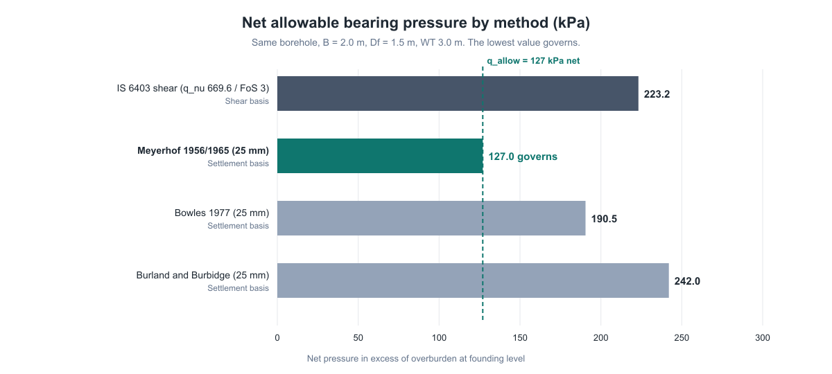
| Method | Basis | N used | Net pressure (kPa) |
|---|---|---|---|
| IS 6403 (q_nu 669.6, FoS 3.0) | Shear | (N1)60 = 15.92 | 223.2 |
| Meyerhof 1956/1965 | Settlement, 25 mm | N60 = 10.5 | 127.0 (governs) |
| Bowles 1977 | Settlement, 25 mm | N60 = 10.5 | 190.5 |
| Burland & Burbidge | Settlement, 25 mm | N̄60 = 10.5 | 242.0 |
Allowable net bearing pressure = 127 kPa (about 12.9 t/m²). Settlement governs, by the Meyerhof method. The gross equivalent is 127 + 25.5 = 152.5 kPa. Burland & Burbidge predicts 223.2 × 0.1033 = 23.1 mm of settlement at the IS 6403 SBC, so it would accept the shear value. Meyerhof would not. That gap is typical of the scatter between methods, discussed next.
Every number in this section matches the engine output to the decimal shown. The engine and the hand calculation agree.
Comparing methods: why the SBC values scatter
The same borehole gives 127 to 242 kPa. That spread is normal and is not an error:
- Meyerhof dates from the 1950s and is deliberately conservative. Field observations later showed it overpredicts settlement, which is why Bowles raised it by about 50 %.
- Burland & Burbidge is based on a much larger database of measured settlements. It is the method in EN 1997-2 Annex F.
- IS 6403 uses a global factor of safety and says nothing about settlement on its own.
Adopting the minimum, as the module does, is the conservative default. If a lower SBC would force you from isolated footings to a raft, you have a case for more investigation (plate load test, CPT) before deciding. The module also says what it does not do: it does not apply EC7 partial-factor design (DA1/DA2) or LRFD resistance factors. The values are IS-style allowable pressures. For a quick IS 6403 check with your own φ and c values, use the IS 6403 bearing capacity calculator.
Codes and references used
| Code / reference | Used for |
|---|---|
| IS 6403:1981 | Net ultimate and net safe bearing capacity, shape, depth and water-table factors (cl 5.1.2) |
| IS 2131:1981 | SPT procedure and the dilatancy correction for fine sand or silt below the water table |
| IS 1893 (Part 1):2016 | Zone factor Z, liquefaction procedure (Annex F), rod-length correction |
| IS 1904:1986 | Permissible settlement (75 mm default for clay; up to 50 mm for isolated footings on sand) |
| EN 1997-2:2007 Annex F.3 | Burland & Burbidge settlement method |
| Meyerhof (1956, 1965); Bowles (1977, 1996) | SPT settlement correlations |
| Youd et al. (2001), NCEER | CRR curve, fines correction, magnitude scaling factor |
Liquefaction screening from SPT (IS 1893)
In Zones III to V, a loose saturated sand under the footing can lose most of its strength during an earthquake, whatever its static SBC. The module screens every saturated, non-plastic layer (sand, silt and gravel with PI < 7) down to 20 m. Each layer is split into slices of 0.5 m or less, and each slice is checked using the simplified procedure:
CSR = 0.65 · (amax/g) · (σv/σ'v) · rd
rd  = 1 − 0.00765·z (z ≤ 9.15 m); 1.174 − 0.0267·z (9.15 < z ≤ 23 m)
CRR7.5 = 1/(34 − N) + N/135 + 50/(10N + 45)² − 1/200,  N = (N1)60cs
CRR = CRR7.5 · MSF · Kσ,  MSF = 10^2.24 / M^2.56  (M = 7.5 → 1.00)
Kσ  = (σ'v/100)^−0.3 ≤ 1  (overburden factor, Youd et al. 2001)
FS  = CRR / CSR
The module takes amax/g = Z, which it attributes to IS 1893 (Part 1):2016 Annex F (Zone IV gives 0.24). Some engineers use Z/2, which halves the CSR and makes the result much less conservative. Pick one deliberately and state it in the report.
Hand check, layer 2 at 4.25 m:
- σv = 25.5 + 18 × 2.75 = 75.0 kPa
- u = 9.81 × 1.25 = 12.26 kPa, so σ'v = 62.74 kPa
- rd = 1 − 0.00765 × 4.25 = 0.9675
- CSR = 0.65 × 0.24 × (75.0/62.74) × 0.9675 = 0.180
- (N1)60 = 10 × 1.05 × 0.85 (CR, 4 to 6 m) × √(100/62.74) = 11.3
- With FC = 18 %: α = e^(1.76 − 190/18²) = 3.23 and β = 0.99 + 18^1.5/1000 = 1.066, so (N1)60cs = 3.23 + 1.066 × 11.3 = 15.3
- CRR = 0.163
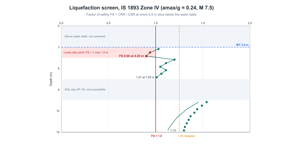
- FS = 0.163 / 0.180 = 0.90
| Layer | Critical depth (m) | (N1)60 | (N1)60cs | CSR | CRR | FS |
|---|---|---|---|---|---|---|
| 1 | – | – | – | – | – | Above WT |
| 2 | 4.25 | 11.3 | 15.3 | 0.180 | 0.163 | 0.90 (liquefiable) |
| 3 | 7.25 | 16.9 | 20.2 | 0.217 | 0.218 | 1.01 (marginal) |
| 4 | – | – | – | – | – | Clay, not susceptible |
| 5 | 14.75 | 23.3 | 23.9 | 0.210 | 0.236 | 1.13 |
Layer 5 is the only screened layer under more than 100 kPa of effective stress, so it is the only one the overburden factor changes. At 14.75 m, σv = 25.5 + 18 × 3 + 18.5 × 3 + 19 × 3 + 19.5 × 4.25 = 274.9 kPa and u = 9.81 × 11.75 = 115.3 kPa, so σ'v = 159.6 kPa and Kσ = (159.6/100)^−0.3 = 0.869. CRR7.5 for (N1)60cs = 23.9 is 0.272, so CRR = 0.272 × 0.869 = 0.236 and FS = 0.236 / 0.210 = 1.13.
FS falls below 1.0 over the lower 1.0 m of layer 2, and the Ishihara–Yoshimine method estimates 22.7 mm of post-earthquake ground settlement. The 127 kPa static value is valid for gravity loads only. For a Zone IV building, this site needs ground improvement (stone columns or vibro-compaction) or piles taken into layer 5. Use the seismic base shear calculator for the superstructure side of the same IS 1893 check.
Common mistakes in SBC calculation from SPT
- Mixing net and gross. A net SBC checked against gross column load plus footing and backfill weight double-counts the overburden. A gross SBC checked against net load does the opposite and is unsafe.
- Using uncorrected N, or the wrong corrected N. φ needs (N1)60. Meyerhof, Bowles and the cu correlation need N60.
- Ignoring footing width. An SBC quoted for a 1.5 m footing does not carry over to a 3 m footing or a raft. Shear SBC rises with B, but the settlement-limited pressure does not.
- Using the water table on the day of boring. Design for the monsoon high. In the example, moving the water table from 3.0 m up to 1.5 m drops W' to 0.5 and Cw to 0.71.
- Averaging N over the whole borehole. Only the soil within about B below the base controls bearing. The settlement check looks deeper.
- Skipping the settlement check. Shear SBC alone overstates capacity on loose sands.
- Treating silty sand as clean sand. Fines change the dilatancy correction below the water table and the liquefaction resistance.
How CivilTech Studio does this
The geotechnical analysis module runs the full chain above from a borehole log:
- Soil profile input. Enter layers with depth, field N, soil type (sand, silt, clay, gravel), bulk unit weight, optional fines %, and LL/PI for clays and silts. You can also import AGS borehole files. A log that starts below ground takes a fill unit weight for the overburden.
- All methods every run. IS 6403 shear, Meyerhof, Bowles, and a Burland & Burbidge (sand) or consolidation (clay) settlement check. The governing net pressure, the governing method, and whether shear or settlement controls are all reported, along with the settlement at the shear SBC.
- Calculations tab. Each step is shown with its formula, substituted values and result, so a reviewer can check it line by line, as in the worked example.
- Liquefaction screening. IS 1893 Zones II to V, slice-by-slice CSR/CRR/FS, fines correction, a plastic-fines screen, and post-liquefaction settlement. A separate Liquefaction Mitigation tab sizes countermeasures.
- Related tabs. CPT-based bearing, rock bearing, ground improvement (stone columns), pile downdrag, pile lateral response and nonlinear load–settlement.
- Hand-off and report. Send the governing SBC, with its net/gross basis, to Foundation Design to size footings. You can also download a PDF calculation report with the same numbers.
Limits you should know: CE, CB and CS are fixed at 1.0, 1.05 and 1.0, the factor of safety is 3.0, and the footing is treated as square. If your SPT hammer energy has been measured, scale N by ER/60 before entering it.
FAQ
How do you calculate safe bearing capacity from SPT N value?
Correct the field N to N60 and (N1)60. Get φ (sand) or cu (clay) from correlations and compute the net ultimate capacity by IS 6403. Divide it by a factor of safety (3.0 in the module) to get the shear SBC. Separately, find the pressure that gives 25 mm of settlement using Meyerhof, Bowles or Burland & Burbidge. The lower of the two is the allowable bearing pressure.
What is a typical SBC for an SPT N value of 10?
For a 2 m footing at 1.5 m depth on silty sand with N = 10, the worked example gives 223 kPa on shear but only 127 kPa for 25 mm of settlement. So about 125 to 130 kPa (12 to 13 t/m²) net. Narrow footings or a deeper water table change this, so always run the specific case.
Is SBC net or gross in IS 6403?
IS 6403 defines both. Net safe bearing capacity is the pressure in excess of the overburden at founding level, and gross = net + γ·Df. Most Indian soil reports quote net. CivilTech Studio reports net throughout and labels it.
Which N value is used in Meyerhof's formula: N60 or (N1)60?
N60. Meyerhof's and Bowles' correlations were developed from field N without overburden correction. Overburden-corrected (N1)60 is used for the friction angle and for liquefaction.
What factor of safety is used for SBC?
The module applies 3.0 to the net ultimate capacity. Indian practice uses 2.5 to 3.0. Settlement-based values have no factor of safety, because they are serviceability limits, not failure loads.
How does the water table affect safe bearing capacity?
It lowers effective stress. IS 6403 multiplies the Nγ term by W', which falls from 1.0 to 0.5 as the water table rises from Df + B to Df. The SPT settlement correlations use Cw = 0.5 + 0.5·Dw/(Df + B). Design for the highest seasonal level.
Can SPT data be used for liquefaction analysis?
Yes. The simplified procedure in IS 1893 (Part 1):2016 Annex F compares the cyclic stress ratio from the earthquake with the cyclic resistance ratio from (N1)60cs. FS below 1.0 means the layer is liquefiable.
Why do Meyerhof and Bowles give different SBC values?
Bowles increased Meyerhof's coefficients by about 50 %, because Meyerhof's original chart overpredicts settlement. Both are shown so you can judge the scatter. The module adopts the lower one.
Educational reference. Always verify against the governing code and your project specification.