#basement-design#is-456#is-3370#retaining-wall#buoyancy#crack-width
Basement Wall Design (IS 456 & IS 3370) — Worked Example
Basement wall design to IS 456 and IS 3370, step by step: at-rest earth and water pressure, propped-wall moments, base slab uplift, the 1.2 flotation check and 0.2 mm crack width, with a full worked example run on the CivilTech Studio engine.
Updated 4 Nov 202622 min read
 Try it free: run this design in Basement DesignOpen →
On this page
- Loads on a basement retaining wall
- Support conditions: propped vs cantilever basement wall
- Step-by-step basement wall design procedure (IS 456 + IS 3370)
- Base slab design for uplift and the flotation check
- Crack width and water-tightness
- Worked example: single-level basement, GWT 1.5 m below ground
- IS code clause reference for basement design
- IS 456 vs ACI 318 vs Eurocode 2 in the module
- Common mistakes in basement wall design
- How CivilTech Studio does this
- FAQ
Basement Wall Design to IS 456 and IS 3370: Pressures, Uplift and Crack Width
By the CivilTech Studio Engineering Team
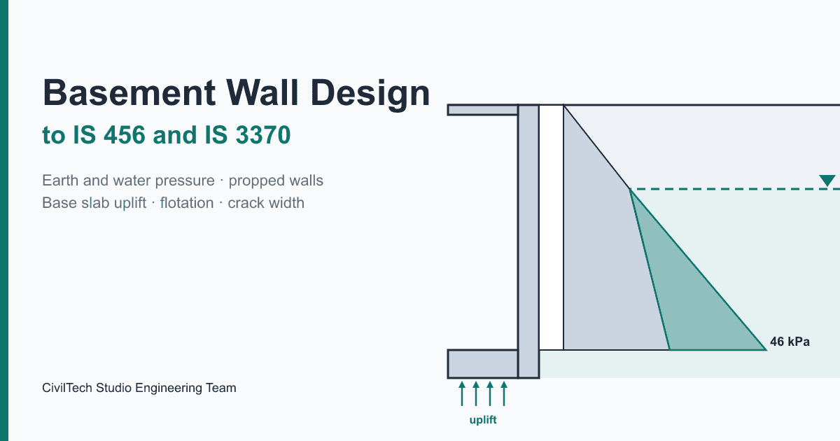
Basement wall design means sizing a reinforced concrete wall that holds back soil, ground water and surcharge, and a base slab that resists the water pushing up from below. Four things usually govern. The first is the lateral pressure: at-rest earth pressure for a wall propped by the ground floor slab, plus full hydrostatic pressure below the water table. The second is the bending and shear this pressure causes, which depends on how the wall is supported. Then come crack width (0.2 mm for a water-retaining section under IS 3370) and flotation: the permanent weight of the box must exceed the uplift by a factor of 1.2. This guide works through each step with formulas. It ends with a full example of a 20 m × 15 m basement, run on the CivilTech Studio basement design module.
Loads on a basement retaining wall
At-rest vs active earth pressure
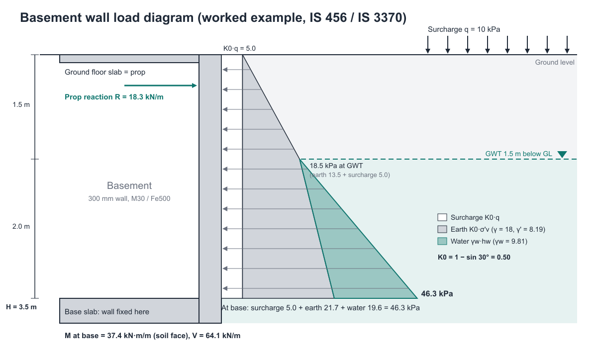
A basement wall is restrained at the top by the ground floor slab and at the bottom by the base slab, so it can barely move. Soil behind a wall that cannot move stays in the at-rest state. The usual coefficient comes from Jaky's formula:
K0 = 1 − sin φ          (φ = 30°  →  K0 = 0.50)
Ka = (1 − sin φ) / (1 + sin φ)   (φ = 30°  →  Ka = 0.333)
Active pressure (Ka) only develops when the wall can rotate or slide away from the soil enough for the fill to fail. That describes a free cantilever wall, not a propped one. With φ = 30°, using Ka in place of K0 cuts the earth pressure by a third.
Soil below the water table: submerged weight plus water
Below the ground water table (GWT), compute the earth pressure from effective stress, which uses the submerged unit weight γ' = γ − γw. Then add the full water pressure on top, because water pushes equally in all directions (K = 1):
Above GWT (depth z ≤ hw0):   p_earth = K · γ · z
Below GWT:                   p_earth = K · (γ · hw0 + γ' · (z − hw0))
                             p_water = γw · (z − hw0)
Surcharge (uniform):         p_q     = K · q
Here hw0 is the depth of the GWT below ground, and γw = 9.81 kN/m³.
Surcharge
Traffic, stacked material or an adjacent footing near the wall adds a uniform pressure K·q over the full height. For a basement next to a road or a parking ramp, 10 kPa is a common minimum. Concentrated loads from neighbouring foundations need their own check.
Seismic increment
In a seismic zone the wall also takes a dynamic earth-pressure increment. A non-yielding (propped) wall is usually checked with the rigid-wall increment of EN 1998-5 Annex E.9 (Wood's solution), ΔP = kh·γ·H² acting at mid-height. A yielding wall uses the Mononobe-Okabe increment, which IS 1893:1984 Cl 8.1 gives as Ca − Ka. Both are covered in the worked example below.
Support conditions: propped vs cantilever basement wall
The support condition sets both the pressure coefficient and the shape of the bending moment diagram.
| Wall type | When it applies | Pressure | Model | Moment pattern |
|---|---|---|---|---|
| Propped | Ground floor slab cast and tied into the wall | K0 | Fixed at base slab, pinned at ground slab | Hogging at base (soil face), sagging in span (inner face) |
| Cantilever | No slab at the top, or the wall is backfilled before the slab is cast | Ka | Fixed at base, free at top | Hogging only, largest at base |
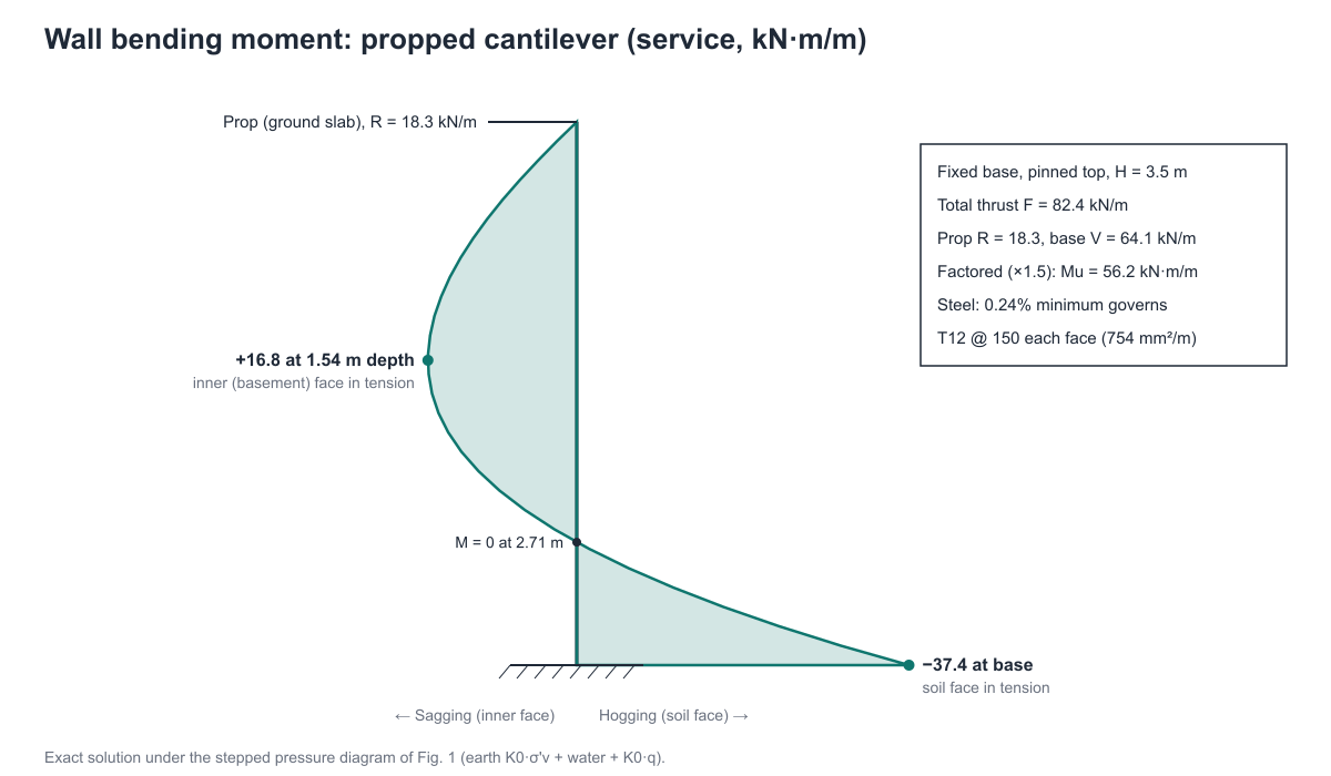
For a uniform load w on a propped cantilever of height H, the prop reaction is 3wH/8, the base moment is wH²/8 and the largest span moment is 9wH²/128. For a triangular load rising from zero at the top to w0 at the base, the prop reaction is w0H/10 and the base moment is w0H²/15. A real basement pressure diagram is stepped at the water table, so you either superpose these cases or integrate the actual diagram.
Even with the higher K0, a propped wall carries far less moment than a cantilever: about half, in the example below. Two cautions follow from the propped model:
- The inner face is in tension over the upper part of the wall, so it needs designed steel, not just nominal bars.
- If the wall is backfilled before the ground slab is cast, it acts as a cantilever during construction. Either check that stage or forbid backfilling until the slab is in place.
Step-by-step basement wall design procedure (IS 456 + IS 3370)
-
Fix geometry and ground data. Depth H, plan size, GWT depth, γ, φ, surcharge, safe bearing capacity. Take the highest credible water table, not the one measured in the dry season.
-
Choose K. Use K0 for a propped wall and Ka for a cantilever.
-
Build the pressure diagram. Use the formulas above, with γ' below the GWT and water added separately.
-
Analyse the wall strip (1 m run). Find the prop reaction, base moment, span moment and base shear.
-
Factor the actions. IS 456 Table 18 uses 1.5 on earth, water and surcharge.
-
Design both faces for flexure. Use the IS 456 limit-state equation, then compare with the minimum steel for a water-retaining section:
Mu = 0.87 fy Ast d (1 − Ast fy / (b d fck)) Ast = (0.5 fck / fy) · [1 − √(1 − 4.6 Mu / (fck b d²))] · b d -
Check one-way shear against τc from IS 456 Table 19. Basement walls carry no shear links, so the wall thickness has to work in shear on its own.
-
Check crack width at service moment against the 0.2 mm limit, and refine bar size and spacing if needed.
-
Design the base slab for net uplift and for the superimposed loads, and check punching under any columns.
-
Check flotation, both in service and at each construction stage.
-
Check bearing, and check sliding and overturning only if the lateral load is unbalanced.
Base slab design for uplift and the flotation check
Uplift pressure and base slab bending
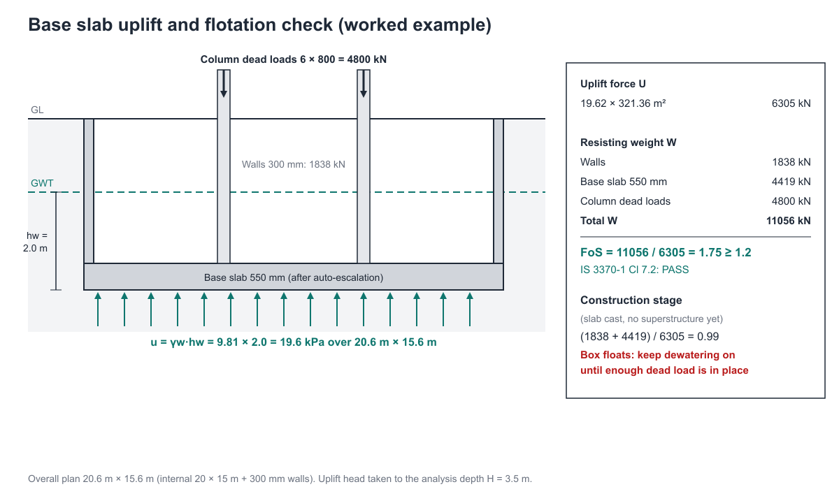
Water at depth hw below the GWT pushes up on the slab soffit with a pressure of:
u = γw · hw
Measure hw to the underside of the base slab, not to its top. The slab's own weight acts against u, so the net upward load at service is u − 25·t. For ultimate design, IS 456 Table 18 allows only 0.9 on dead load where it relieves the load:
net factored uplift = 1.5 · u − 0.9 · (25 · t)
The base slab must also carry the superimposed loads that bear on the soil (columns, floor loads), so design it for whichever of the two cases gives the larger pressure.
Flotation (buoyancy) factor of safety
The whole box must not float:
FoS_uplift = Σ permanent weight / (γw · hw · A_base) ≥ 1.2
IS 3370 (Part 1):2009 Cl 7.2 calls for 1.2. Only permanent loads count: concrete self-weight, permanent finishes and the dead part of column loads. Live load can be absent on the day the water table peaks, so leave it out.
Construction-stage flotation
The worst moment usually comes before the superstructure exists. Once the base slab and walls are cast, the box may weigh less than the water it displaces. Common Indian site practice is to keep the dewatering wells running until enough dead load is in place, and to provide relief or flood openings as a fallback. Tension piles or a thicker slab are the permanent alternatives.
Crack width and water-tightness
A basement in a high water table is a water-retaining structure, even though the water is outside. IS 3370 (Part 2) limits surface crack width to 0.2 mm for such members. Check crack width under service moments, not factored ones. The IS 456 Annex F method calculates it from the steel strain at the tension face, the distance to the nearest bar (acr) and the cover:
w = 3 · acr · εm / (1 + 2 (acr − c_min) / (h − x))
εm = ε1 − b (h − x)² / (3 Es As (d − x))
Smaller bars at closer spacing lower acr and the crack width. In practice, crack control often decides the bar layout once the strength steel is known. Water-tightness also depends on detailing that no calculation captures: PVC waterstops at construction joints, a cast-in kicker for the wall starter, a w/c ratio of 0.45 or less, good compaction and proper curing.
Worked example: single-level basement, GWT 1.5 m below ground
The numbers below come from running the CivilTech Studio basement engine, and each key value is checked by hand.
Inputs
| Item | Value |
|---|---|
| Basement depth H (ground to formation) | 3.5 m |
| Internal plan | 20 m × 15 m (overall 20.6 m × 15.6 m with 300 mm walls) |
| Wall | 300 mm, propped by the ground floor slab, fixed at the base slab |
| Base slab | 400 mm trial (the module escalated it, see below) |
| Soil | γ = 18 kN/m³, φ = 30°, c = 0 |
| GWT | 1.5 m below ground level |
| Surcharge | 10 kPa |
| Materials | M30, Fe500, 50 mm cover |
| Columns on the raft | 6 no., 450 × 450, 1200 kN service each, of which 800 kN is dead load |
| SBC | 200 kPa |
| Code | IS 456 + IS 3370, water-retaining |
Step 1: pressures
K0 = 1 − sin 30° = 0.50          γ' = 18 − 9.81 = 8.19 kN/m³
Surcharge:  K0 · q = 0.5 × 10 = 5.0 kPa
At GWT (1.5 m): earth = 0.5 × 18 × 1.5 = 13.5 kPa   → total 18.5 kPa
At base (3.5 m):
  earth = 0.5 × (18 × 1.5 + 8.19 × 2.0) = 0.5 × 43.38 = 21.69 kPa
  water = 9.81 × 2.0                                  = 19.62 kPa
  total = 21.69 + 19.62 + 5.0                         = 46.31 kPa
The engine reports K0 = 0.50 and 21.69 / 19.62 / 5.0 / 46.31 kPa, which match.
Step 2: wall moments (propped cantilever, clear span 2.95 m)
The wall spans from the ground slab down to the top of the base slab, so with the 550 mm base the module settles on (Step 4) its clear span is H_c = 3.5 − 0.55 = 2.95 m. The pressure at the base of that span is 38.66 kPa (earth 19.44 + water 14.22 + surcharge 5.0).
Integrate the stepped diagram over the span (prop at the top, fixed at the slab):
Prop reaction      R = ∫ p(z) · s²(3H_c − s) / (2H_c³) dz = 13.64 kN/m   (s = H_c − z)
Thrust             F = ∫ p(z) dz                          = 59.07 kN/m
Base moment   M_base = ∫ p(z) · s dz − R · H_c            = 22.51 kN·m/m (soil face)
Base shear         V = F − R                              = 45.42 kN/m at the slab face
                                                          = 36.5 kN/m at d from it (IS 456 Cl 22.6.2)
Span moment   +10.22 kN·m/m at 1.27 m depth (inner face)
The engine solves the wall exactly and reports the same: R = 13.6, M_base = 22.51, M_span = +10.22 at 1.27 m, V = 36.47 kN/m.
Step 3: steel, shear and crack width
Mu = 1.5 × 22.51 = 33.8 kN·m/m,  d = 300 − 50 − 8 = 242 mm
Ast = 0.03 × (1 − √(1 − 4.6 × 33.8e6 / (30 × 1000 × 242²))) × 1000 × 242
    = 329 mm²/m
Minimum, IS 3370-2 Cl 8.1.1: 0.35 % of each surface zone (the 20 m side is over 15 m,
so the 0.24 % reduction does not apply); surface zone = 300 / 2 = 150 mm per face
    = 0.0035 × 150 × 1000 = 525 mm²/m per face  → governs
Provide T12 @ 200 = 565 mm²/m on each face; horizontal T12 @ 200 each face
The 0.35 % is of the whole section, split between the two faces: 1050 mm²/m in total, 525 per face. Shear passes comfortably:
Vu = 1.5 × 36.47 = 54.7 kN/m     τv = 54.7e3 / (1000 × 242) = 0.23 MPa
pt = 565 / (1000 × 242) = 0.23 %  → τc (IS 456 Table 19, M30) ≈ 0.34 MPa  → passes
Crack width at the soil face, with service M = 22.51 kN·m/m and Ec = 5000√30:
m = 7.30, ρ = 0.00234  →  x = 40.8 mm, lever arm = 228.4 mm
fs = 22.51e6 / (565 × 228.4) = 174 MPa,  εs = 0.00087
ε1 = 0.00087 × (300 − 40.8) / (242 − 40.8) = 0.00112
εm = 0.00112 − 1000 × 259.2² / (3 × 2e5 × 565 × 201.2) = 0.00014
acr = √(100² + 56²) − 6 = 108.6 mm
w = 3 × 108.6 × 0.00014 / (1 + 2 × (108.6 − 50) / 259.2) = 0.031 mm  < 0.2
The engine gives 0.031 mm.
Step 4: base slab
The base slab is a two-way panel between the walls: IS 456 Annex D, Table 26 case 9 (four edges discontinuous; the corners are held down by the walls). The columns are not taken as supports. The effective spans are the centre-to-centre spans (Cl 22.2(a)): lx = 15.30 m and ly = 20.30 m, so ly/lx = 1.33 and αx = 0.0806. For the load it takes the larger of the net uplift and the superimposed loads spread over the raft:
Uplift case:   1.5 × 19.62 − 0.9 × 25 × 0.55            = 17.06 kPa
Bearing case:  (1.5 × 7200 + 1.5 × 8 × 300) / 321.36    = 44.81 kPa  → governs
Mu = αx · w · lx² = 0.0806 × 44.81 × 15.30²             = 845.5 kN·m/m
d  = 550 − 50 − 32/2 = 484 mm (designed at the depth of the bars it picks)
Ast = 0.03 × (1 − √(1 − 4.6 × 845.5e6 / (30 × 1000 × 484²))) × 1000 × 484
    = 4817 mm²/m
The module provides T32 @ 100 (8042 mm²/m) top and bottom, the lightest layout that also keeps the service crack width (M = 0.0806 × 29.87 × 15.30² = 563.7 kN·m/m) within the limit: 0.169 mm < 0.2. That much steel puts the neutral axis past xu,max, so the capacity is taken as Mu,lim = 0.133 × 30 × 1000 × 484² = 933 kN·m/m (IS 456 Annex G), still above 845.5. At the 400 mm trial thickness, slab flexure, shear, crack width and punching all failed; the module raised the slab to 550 mm, where punching drops to 0.73.
Read this result carefully. The interior columns count toward bearing, punching and flotation weight, but the module does not treat them as supports for the slab. For a 15 m wide box on a 5 m column grid, 550 mm with T32 @ 100 is therefore an upper bound. A raft or flat-slab analysis between column lines will normally give a much lighter slab. Use the module for the walls, the flotation check and a first-pass slab thickness, and design the raft between columns separately.
Step 5: flotation, bearing and construction stages
Uplift  U = 9.81 × 2.0 × (20.6 × 15.6) = 19.62 × 321.36 = 6305 kN
Walls     = 2 × (20.3 + 15.3) × 0.3 × 2.95 × 25         = 1575 kN  (centre-line, slab top to ground)
Base slab = 321.36 × 0.55 × 25                         = 4419 kN
Columns (dead part only) = 6 × 800                     = 4800 kN
FoS = (1575 + 4419 + 4800) / 6305 = 10794 / 6305 = 1.71 ≥ 1.2
Bearing: (1575 + 4419 + 7200 + 8 × 300) / 321.36 = 48.5 kPa, well under 200 kPa. The box is enclosed, so the earth pressures on opposite walls balance and the module reports sliding and overturning as not applicable.
The construction-staging option tells a different story. With the walls and slab cast but no superstructure yet, FoS = (1575 + 4419) / 6305 = 0.95. The box would float if dewatering stopped. The critical earlier stage, with the excavation open, is 0.30.
Results summary
| Check | Value | Limit | Result |
|---|---|---|---|
| Lateral pressure at base | 46.31 kPa | — | — |
| Wall M (service): base / span | 22.51 / 10.22 kN·m/m | — | — |
| Wall steel, soil face | T12 @ 200 (565 mm²/m) | ≥ 525 mm²/m per face | Pass |
| Wall steel, inner face | T12 @ 200 | ≥ 525 mm²/m per face | Pass |
| Wall shear | Vu 54.7 kN/m, τv 0.23 MPa | τc ≈ 0.34 MPa | Pass |
| Wall crack width | 0.031 mm | 0.2 mm | Pass |
| Base slab (auto-sized) | 550 mm, T32 @ 100 | Mu 845.5 ≤ 933 kN·m/m | Pass |
| Base slab crack width | 0.169 mm | 0.2 mm | Pass |
| Punching, worst column | 0.73 | ≤ 1.0 | Pass |
| Flotation FoS, in service | 1.71 | ≥ 1.2 | Pass |
| Flotation FoS, slab cast, no superstructure | 0.95 | ≥ 1.05 (staging) | Fail: keep dewatering on |
| Bearing | 48.5 kPa | 200 kPa | Pass |
Same box, three other choices
- Cantilever wall (Ka = 0.333). The base pressure drops to 37.4 kPa, but the base moment rises to 43.5 kN·m/m and the soil face needs T12 @ 150 (649 mm²/m required). Releasing the prop hurts far more than the lower K helps.
- Columns not counted against uplift. At the 400 mm trial the box is 2697 kN short of FoS 1.2. The module makes up the weight with concrete: the base slab grows to 800 mm for FoS = (1442 + 6427) / 6305 = 1.25. It also lists what else would do the job: a base toe projecting 0.84 m all round (the soil on it holds 42.3 kN/m² net), or tension anchors for 2697 kN (18 at 150 kN or 9 at 300 kN working).
- Seismic zone III, rigid-wall increment. kh = Z/2 × I = 0.08, so ΔP = 0.08 × (18 × 1.5 + 18.0 × 2.0) × 3.5 = 17.6 kN/m (over the full depth) at mid-height, taking the saturated weight 8.19 + 9.81 = 18.0 kN/m³ below the GWT. The wall steel is unchanged because minimum steel still governs. However, the IS 456 limit-state sliding check (0.9 DL − uplift, 1.5 EL, base friction only) reaches only 0.91 even with an 800 mm slab, and the design is reported as failing. The service sliding FoS is 1.70. The module does not count passive resistance from the soil against the opposite wall, so treat this as a prompt to add a shear key, use tension piles or run a closer soil-structure check.
IS code clause reference for basement design
| Topic | Reference | How it is used |
|---|---|---|
| Load factors 1.5, and 0.9 on dead load where it helps | IS 456:2000 Table 18 | Wall and slab ultimate actions; net uplift on the slab |
| Overturning: restoring ≥ 1.2 × DL overturning, with 0.9 × restoring DL | IS 456:2000 Cl 20.1 | Seismic limit-state stability |
| Design shear strength τc | IS 456:2000 Table 19 | Wall and slab one-way shear |
| Punching shear, ks·0.25√fck | IS 456:2000 Cl 31.6 | Columns on the base slab |
| Crack width | IS 456:2000 Annex F | Wall faces and base slab |
| Flotation FoS 1.2 | IS 3370 (Part 1):2009 Cl 7.2 | Uplift check |
| Crack width limit 0.2 mm | IS 3370 (Part 2):2009 | Water-retaining sections |
| Zone factor Z, design acceleration | IS 1893 (Part 1):2016 Cl 6.4.2 | kh and box inertia |
| Mononobe-Okabe for yielding walls | IS 1893:1984 Cl 8.1 | Cantilever or flexible walls (now covered by IS 1893 Part 3) |
| Rigid-wall seismic increment | EN 1998-5:2004 Annex E.9 | Propped (non-yielding) walls |
IS 456 vs ACI 318 vs Eurocode 2 in the module
The same basement can be run to three code sets. These are the defaults the engine applies:
| Item | IS 456 + IS 3370 | ACI 318-19 + ACI 350 | EN 1992-1-1 + EN 1992-3 |
|---|---|---|---|
| Factor on earth and water | 1.5 | 1.6 | 1.35 |
| Factor on surcharge | 1.5 | 1.6 | 1.5 |
| Favourable self-weight on uplift | 0.9 | 0.9 | 1.0 |
| Minimum steel, water-retaining (whole section, split between faces) | 0.35% of the surface zones (0.24% if no dimension > 15 m) | 0.30% | 0.20% |
| Crack limit, water-retaining | 0.2 mm | 0.25 mm | 0.2 mm |
| Crack limit, normal | 0.3 mm | 0.41 mm | 0.3 mm |
| Crack width method | IS 456 Annex F | Gergely-Lutz (ACI 224R) | EC2 Eq. 7.8 |
| One-way shear | Table 19 τc | Table 22.5.5.1 | Eq. 6.2a |
| Flotation FoS | 1.2 | 1.2 | 1.2 |
| Seismic stability | Service FoS + 0.9 DL ± 1.5 EL limit state | Service FoS | Service FoS |
Common mistakes in basement wall design
- Using Ka for a propped wall. A wall held by slabs does not move enough to reach the active state. With φ = 30°, Ka understates the earth pressure by 33%.
- Bulk density below the water table, and no water pressure. Taking γ = 18 kN/m³ over the full height with no water gives 36.5 kPa at the base of the example wall, against the correct 46.3 kPa: 21% low.
- Applying the minimum steel to each face. The IS 3370-2 minimum (0.35 %, or 0.24 % when no dimension exceeds 15 m) is of each surface zone, half the thickness per face. For the 300 mm example wall that is 525 mm²/m per face, not 1050.
- Measuring the uplift head to the slab top. Water acts on the soffit, so measure hw to the formation level.
- Counting live load or full column loads against flotation. Only permanent load resists uplift. In the example, 4800 kN of the 7200 kN column load counts.
- Ignoring construction-stage flotation. A box that passes at 1.71 in service can sit at 0.95 the day the slab is cast.
- Designing only the soil face. A propped wall has a sagging moment on the inner face. Here it is 10.2 kN·m/m at 1.27 m depth.
- Checking cracks at ultimate stress, or ignoring them. Crack width uses service moments, and often decides bar spacing.
- A one-sided sliding check on an enclosed box. Balanced earth pressures cancel through the slabs. Sliding and overturning matter for open, partly backfilled or sloping-site boxes, and under seismic load.
How CivilTech Studio does this
The basement design calculator covers the workflow above in one model:
- Three code sets: IS 456 + IS 3370, ACI 318-19 + ACI 350, or EN 1992-1-1 + EN 1992-3, each with its own load factors, minimum steel, crack method and limits.
- Propped or cantilever walls: K0 is used for a propped wall and Ka for a cantilever. The wall is solved exactly under the stepped pressure diagram, and both faces are designed.
- Multi-level basements: the wall is solved as one continuous strip, propped at each floor and fixed at the base, and every level gets its own steel and governing combination.
- Bar selection: the module picks the lightest bar layout that meets both the strength steel and the crack-width limit.
- Base slab: designed as a two-way panel (IS 456 Table 26) for net uplift and superimposed load, at the depth of the bars it picks, with punching under each column you enter. Only the dead part of each column load resists uplift, and a column without a dead load is not counted unless you set a fallback share.
- Stability: flotation (FoS 1.2), bearing, and sliding and overturning (FoS 1.5) for boxes marked as unbalanced.
- Optional seismic check: Mononobe-Okabe for yielding walls or the rigid-wall increment for propped walls, plus IS 456 limit-state stability.
- Optional extras: settlement, a dewatering estimate (seepage, wells, sump) and a five-phase construction-staging check of interim flotation.
- Auto-escalation: failing checks increase the wall or slab thickness up to the maximum you set. When uplift drives the slab thicker, the module also gives the toe width or anchor tension that would do instead.
- Outputs: a bar bending schedule, material quantities and a calculation report.
For the free-standing case, the retaining wall design module handles cantilever walls with heel and toe. For water held inside rather than outside, see water tank design. To set the SBC, start with bearing capacity.
FAQ
What earth pressure coefficient should I use for a basement wall? Use K0 = 1 − sin φ for a wall propped by floor slabs, since it cannot move enough to mobilise active pressure. Use Ka only for a free cantilever wall. For φ = 30°, K0 = 0.50 and Ka = 0.333.
How do you calculate uplift pressure on a basement slab? Multiply the unit weight of water by the head from the highest water table to the underside of the slab: u = 9.81 × hw kPa. A 2.0 m head gives 19.62 kPa.
What factor of safety against flotation is required for a basement? IS 3370 (Part 1):2009 Cl 7.2 requires 1.2 on the permanent weight against total uplift. Do not count live load. Count only the dead part of the superstructure load, and check the construction stage before that load exists.
What crack width is allowed in a basement wall? For water-retaining sections, IS 3370 limits crack width to 0.2 mm, and the module uses that as the IS default. The ACI 350 path uses 0.25 mm and the EN 1992-3 path 0.2 mm. Check crack width at service moments.
Is the minimum steel for a basement wall different from a normal wall? Yes. For a water-retaining basement to IS 456 + IS 3370, IS 3370-2 Cl 8.1.1 asks for 0.35% of each surface zone with HYSD bars (0.24% when no dimension of the structure exceeds 15 m), compared with 0.12% for a normal section. The surface zone is half the thickness on each face up to 500 mm. In the example, this minimum governed the 300 mm wall: 525 mm²/m, T12 @ 200 on each face.
Do I need to check sliding and overturning for a basement? For a fully enclosed, evenly backfilled box, the earth pressures on opposite walls balance and there is no net sliding force. Check sliding and overturning for open, partly backfilled or sloping-site basements, and under seismic load.
How can I stop a basement floating during construction? Keep dewatering running until enough dead load is in place. Alternatively, thicken the base slab, add ballast or use tension piles. Run the staging check in the basement design tool to see which phase is critical.
Educational reference. Always verify against the governing code and your project specification.