#shear-wall#is-13920#is-456#seismic-design#boundary-element#rcc-design
Shear Wall Design (IS 13920) — P–M & Boundary Example
Shear wall design to IS 13920 step by step: boundary-element stress trigger, P–M interaction, in-plane shear with τc,max cap, minimum steel and spacing, plus a fully worked 3000 × 250 mm M30 wall checked by hand and in software.
Updated 4 Nov 202617 min read
 Try it free: run this design in RC Shear Wall / Core DesignerOpen →
On this page
- What governs shear wall design in India
- Step-by-step shear wall design calculation
- Worked example: 3000 × 250 mm shear wall, M30 / Fe 500
- IS 13920 vs ACI 318 vs Eurocode 2: the same wall under three codes
- Shear wall code clause reference
- Common mistakes in IS 13920 shear wall design
- How CivilTech Studio does this
- Frequently asked questions
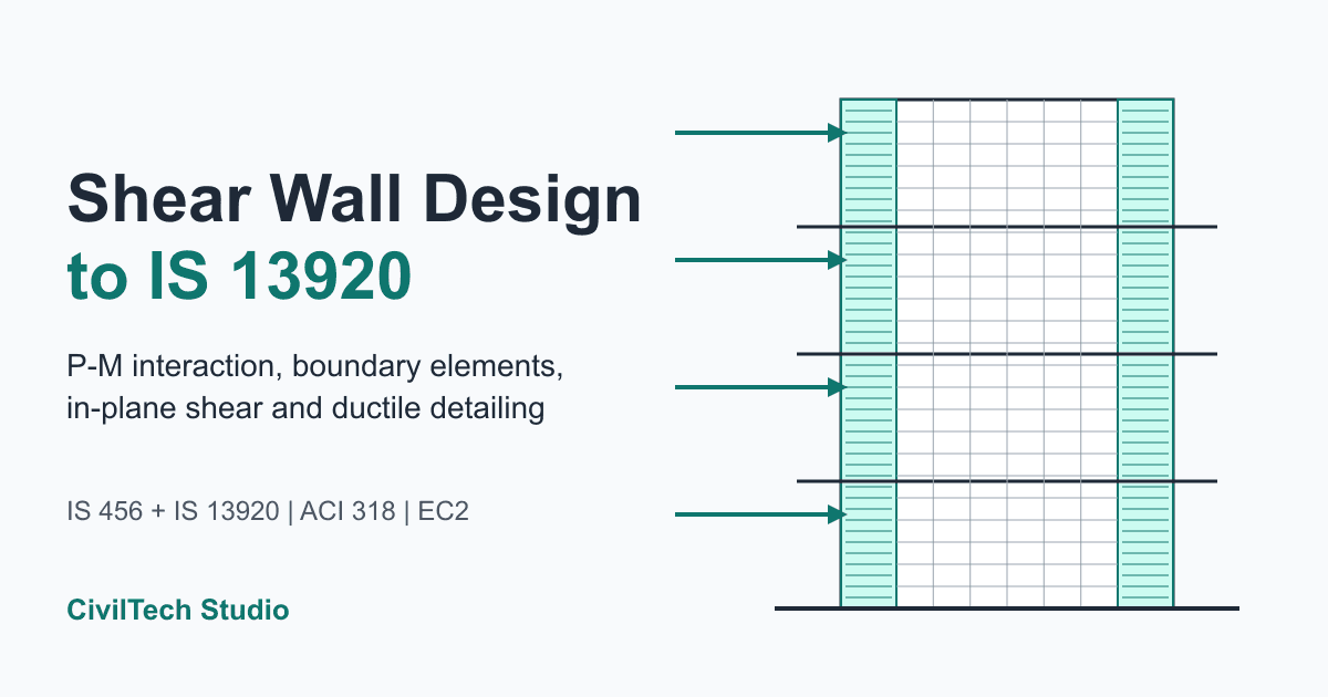
Shear wall design to IS 13920:2016 comes down to four checks on the factored seismic combination. First, the in-plane axial load and moment (Pu, Mu) must sit inside the wall's P–M interaction curve, built from the distributed web steel plus the boundary bars. Second, the in-plane shear stress τv = Vu/(tw·0.8lw) must be carried by concrete τc plus horizontal steel, and must not exceed τc,max. Third, special boundary elements are required when the extreme-fibre stress Pu/Ag + Mu/Z exceeds 0.2·fck. Fourth, the detailing must comply: tw ≥ 150 mm, at least 0.25 % steel each way, bar spacing no more than min(lw/5, 3tw, 450 mm), and two curtains when tw ≥ 200 mm. This guide takes each step in turn, then designs a 3000 × 250 mm M30 wall carrying Pu = 3500 kN, Mu = 4500 kN·m and Vu = 900 kN. The working is checked by hand and against the CivilTech Studio shear wall design calculator.
By the CivilTech Studio Engineering Team
What governs shear wall design in India
A shear wall is a vertical cantilever. In-plane bending makes one end crush and the other end yield in tension, while the storey shear tries to crack the web diagonally and slide the wall on its base joint. Indian practice uses two codes together:
- IS 456:2000 gives the limit-state basis: the rectangular stress block (0.36·fck, εcu = 0.0035, steel at 0.87·fy), the squash load Puz (Cl 39.6), the shear strengths τc (Table 19) and τc,max (Table 20), and the minimum steel for ordinary walls (Cl 32.5).
- IS 13920:2016 Clause 10 turns an ordinary wall into a special shear wall for ductile seismic behaviour. It covers minimum thickness, the 0.25 % minimum steel, bar spacing, two curtains, the in-plane shear check, and boundary elements (Cl 10.4).
A slender wall (hw/lw well above 2) acts in flexure like a very deep column. That is why the in-plane check is a P–M interaction about the strong axis, with the wall thickness tw as the section width. The demands come from your analysis: base shear to IS 1893 (the seismic base shear calculator gives Ah and Vb for a quick check) combined using the IS 1893 / IS 456 load combinations. Typical governing cases are 1.2(DL + LL ± EQ), plus 0.9DL ± 1.5EQ when axial load is low.
Step-by-step shear wall design calculation
Step 1: Section and minimum thickness
Choose lw, tw and the grade. IS 13920 sets a minimum of 150 mm for special shear walls. In practice 200–300 mm is used for buildings above about eight storeys. A 230 mm wall lines up with brickwork, and 250 mm or more leaves room for two curtains plus boundary-element hoops.
Step 2: Boundary element trigger (0.2·fck)
Work out the extreme-fibre compressive stress on the gross section, assuming a linearly elastic section:
σ = Pu/Ag + Mu·(lw/2)/Ig = Pu/(lw·tw) + Mu/(tw·lw²/6)
Special boundary element required if σ > 0.2·fck
May be discontinued where σ < 0.15·fck
This is a screening check on the factored seismic combination, not an actual stress. It tells you whether the wall ends need column-like confinement. The boundary-element length is still your decision (see Step 5).
Step 3: P–M interaction by strain compatibility
Split the vertical steel into layers: the distributed web bars (both curtains lumped) spread along the web, plus one concentrated layer of boundary bars at each end. Then sweep the neutral-axis depth xu from deep compression to pure tension. For each xu, add up the concrete block force and every layer's steel force from its strain, ε(y) = 0.0035·(xu − y)/xu. That gives one (Pn, Mn) point per xu. Join the points to get the interaction curve, cap the top at Puz = 0.45·fck·Ac + 0.75·fy·Asc, and read Mn at your Pu.
Flexure OK if Mn(Pu) ≥ Mu and Pu ≤ Puz
Do not count web steel that sits inside the boundary zones a second time. If the boundary bars are modelled separately, the distributed steel covers only the web between them (lw − 2·Lbe).
Step 4: In-plane shear (IS 13920 Cl 10.2 with IS 456 Tables 19 and 20)
d    = 0.8·lw                       (effective depth for in-plane shear)
τv   = Vu / (tw·d)
Vc   = τc·tw·d                      τc from IS 456 Table 19 at pt = 100·ρv
Vs   = 0.87·fy·Ah·d / sv            Ah = area of horizontal bars at spacing sv (both curtains)
     = 0.87·fy·ρh·tw·d
Vmax = τc,max·tw·d                  τc,max from IS 456 Table 20 (3.5 MPa for M30)
Shear OK if Vu ≤ min(Vc + Vs, Vmax)
For a seismic wall the IS 456 Cl 40.2.2 enhancement of τc for axial compression is not applied. If Vu is above Vmax, extra horizontal steel will not help. Thicken or lengthen the wall instead.
Step 5: Boundary element detailing
Where Step 2 calls for a boundary element:
- vertical steel at least 0.8 % of the boundary-element area (6 % maximum);
- confining hoops at spacing no more than min(¼ of the boundary-element thickness, 6 × the smallest longitudinal bar diameter, 100 mm);
- each hoop leg at least
Ash = 0.05·sv·h·fck/fy, where h is the longer side of the hoop measured to its outer face. Crossties reduce h.
Common Indian practice is a flush boundary element: the same thickness as the wall, extending 0.15–0.2·lw from each end, or over the length where the elastic stress exceeds 0.2·fck.
Step 6: Minimum reinforcement and spacing
- ρv and ρh at least 0.25 % of the gross web area (IS 13920 Cl 10.1). Non-seismic walls follow the lower IS 456 Cl 32.5 minima.
- Maximum spacing of each curtain is
min(lw/5, 3·tw, 450 mm). - Two curtains are needed when tw ≥ 200 mm, or when τv > 0.25·√fck.
Step 7: Base sliding (shear friction)
At the base construction joint, the vertical bars crossing the joint plus the coexisting compression resist sliding:
Vn,slide = μ·(Ast·fy + N) ≤ 0.2·fck·Ag μ = 1.0 for an intentionally roughened joint
Only permanent compression should go into N, not the full factored Pu.
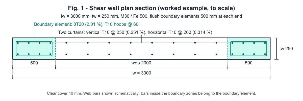
Worked example: 3000 × 250 mm shear wall, M30 / Fe 500
The wall is a planar wall at the base of a G+11 residential tower in Zone IV, with storey height 3 m, so hw = 36 m and hw/lw = 12. The factored seismic combination gives Pu = 3500 kN, Mu = 4500 kN·m and Vu = 900 kN. The permanent axial load used for sliding is taken as 2400 kN.
| Input | Value |
|---|---|
| Wall length lw / thickness tw / clear cover | 3000 / 250 / 40 mm |
| Concrete / steel | M30 / Fe 500 |
| Boundary elements | flush, 500 mm long at each end, 8T20 each, T10 hoops @ 60 mm (no crossties) |
| Web vertical steel | T10 @ 250 mm, two curtains: ρv = 2 × 78.5/(250 × 250) = 0.251 % |
| Web horizontal steel | T10 @ 200 mm, two curtains: ρh = 2 × 78.5/(250 × 200) = 0.314 % |
| Factored actions | Pu = 3500 kN, Mu = 4500 kN·m, Vu = 900 kN |
| Seismic detailing | IS 13920 on |
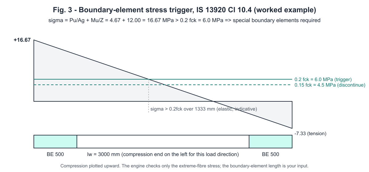
Boundary element trigger
Ag = 3000 × 250 = 750,000 mm²
Z  = 250 × 3000² / 6 = 375 × 10⁶ mm³
σ  = 3,500,000/750,000 + 4,500 × 10⁶/375 × 10⁶ = 4.67 + 12.00 = 16.67 MPa
0.2·fck = 6.0 MPa  →  16.67 > 6.0, special boundary elements REQUIRED
Boundary elements can only stop higher up, once σ falls below 0.15·fck = 4.5 MPa. With Pu falling and Mu dropping quickly up the height, this usually happens several storeys above the base, but you have to check it storey by storey.
Boundary element confinement
BE steel: 8T20 = 2513 mm² on 500 × 250 = 125,000 mm²  →  2.01 %  (0.8–6 %, OK)
Hoop spacing limit = min(250/4, 6 × 20, 100) = min(62.5, 120, 100) = 62.5 mm  →  provide 60 mm
h (no crossties) = 500 − 2 × 40 = 420 mm
Ash = 0.05 × 60 × 420 × 30/500 = 75.6 mm²  ≤  78.5 mm² (one T10 leg)  OK
The margin is small. A single crosstie at mid-length would halve h and give comfortable spare capacity.
P–M interaction and flexure
Total vertical steel: web 0.251 % × (3000 − 2 × 500) × 250 = 1257 mm², plus 2 × 2513 = 5027 mm² in the boundary elements, so Ast = 6283 mm² (0.84 % of Ag).
Puz = 0.45 × 30 × (750,000 − 6,283) + 0.75 × 500 × 6,283
    = 10,040 kN + 2,356 kN = 12,396 kN       Pu/Puz = 0.282
The strain-compatibility curve from the engine gives Mn(Pu = 3500 kN) = 6371 kN·m, so Mu/Mn = 4500/6371 = 0.706. As an independent check, we solved the same section by hand with elastic-perfectly-plastic steel at 0.87·fy. That gave xu = 1333 mm and Mn = 6458 kN·m, 1.4 % above the engine. The engine uses the IS 456 design stress–strain curve for HYSD steel, which gives lower steel stresses at intermediate strains, so a slightly lower engine value is expected.
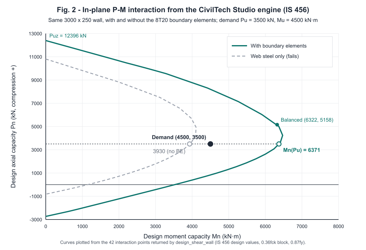
Figure 2 shows why the boundary bars matter. With web steel alone (0.25 % everywhere), the same wall reaches only Mn(Pu) = 3930 kN·m, a utilisation of 1.15, which fails. The 8T20 groups at each end raise flexural capacity by 62 % without any change in thickness.
In-plane shear
d   = 0.8 × 3000 = 2400 mm
τv  = 900,000/(250 × 2400) = 1.50 MPa
τc  (Table 19, M30, pt = 0.251 %) = 0.371 MPa   →  Vc = 0.371 × 250 × 2400 = 222 kN
Vs  = 0.87 × 500 × (2 × 78.5) × 2400/200 = 820 kN
Vmax = 3.5 × 250 × 2400 = 2100 kN
Capacity = min(222 + 820, 2100) = 1042 kN  ≥  900 kN   (utilisation 0.86)
Concrete carries less than a quarter of the shear. The horizontal curtains do the real work. With T10 @ 250 horizontal (ρh = 0.251 %), Vs falls to 656 kN, so Vc + Vs = 878 kN < 900 kN and the wall fails in shear. That is why the horizontal spacing is tighter than the vertical.
Detailing and sliding
- tw = 250 ≥ 150 mm: OK.
- ρv = 0.251 %, ρh = 0.314 %, both ≥ 0.25 %: OK.
- Spacing limit = min(3000/5, 3 × 250, 450) = 450 mm. Provided 250 / 200 mm: OK.
- Two curtains are required on both counts: tw ≥ 200 mm, and τv = 1.50 > 0.25√30 = 1.37 MPa. Provided: OK.
- Sliding: μ(Ast·fy + N) = 1.0 × (3142 + 2400) = 5542 kN, capped at 0.2 × 30 × 750,000 = 4500 kN. Vu/4500 = 0.20: OK.
Results summary (IS 456 + IS 13920)
| Check | Demand | Capacity / limit | Utilisation | Result |
|---|---|---|---|---|
| Axial | Pu = 3500 kN | Puz = 12,396 kN | 0.28 | OK |
| Flexure (P–M) | Mu = 4500 kN·m | Mn(Pu) = 6371 kN·m | 0.71 | OK |
| In-plane shear | Vu = 900 kN | 1042 kN (Vmax 2100 kN) | 0.86 | OK |
| Base sliding | Vu = 900 kN | 4500 kN | 0.20 | OK |
| Boundary element trigger | σ = 16.67 MPa | 0.2·fck = 6.0 MPa | n/a | Required, provided |
| Boundary element confinement | Ash,req = 75.6 mm² | 78.5 mm² per leg; s = 60 ≤ 62.5 mm | 0.96 | OK |
| Minimum steel | 0.251 % / 0.314 % | 0.25 % | n/a | OK |
| Overall | SAFE |
All of these numbers come from one run of the shear wall design tool with the inputs above. The script and its full output are kept with this article.
IS 13920 vs ACI 318 vs Eurocode 2: the same wall under three codes
The module runs the same section under each code, using the same materials (fy = 500 MPa is used throughout for a like-for-like comparison).
| Quantity | IS 456 + IS 13920 | ACI 318-19 §18.10 | EC2 + EC8 (DCM) |
|---|---|---|---|
| Axial cap used | Puz = 12,396 kN | φ·0.80·P0 = 11,495 kN | NRd = 15,375 kN |
| Moment capacity at Pu | 6371 kN·m | φMn = 7451 kN·m | MRd = 6978 kN·m |
| Flexural utilisation | 0.71 | 0.60 | 0.64 |
| Concrete shear Vc | 222 kN | 698 kN (0.17√f′c·Acv) | 589 kN (VRd,c) |
| Steel shear Vs | 820 kN | 1178 kN (ρt·fy·Acv) | 1639 kN (cot θ = 2.5) |
| Shear cap | 2100 kN (τc,max) | 3410 kN (0.83√f′c·Acv) | 1748 kN (VRd,max) |
| Design shear | Vu = 900 kN | Ve = 2700 kN (capped at 3Vu) | ε·Vu = 1.5 × 900 = 1350 kN |
| Usable shear capacity | 1042 kN | φ = 0.75 → 1407 kN | 1748 kN |
| Shear utilisation | 0.86 | 1.92 | 0.77 |
| Max web bar spacing | 450 mm | 450 mm | 400 mm |
| Verdict | SAFE | FAIL (shear) | SAFE |
The big difference is capacity-design shear. ACI 318 §18.10.3 amplifies Vu by the flexural overstrength (Mpr at 1.25·fy) and a dynamic factor for tall walls. Here that reaches the 3Vu ceiling, so Ve = 2700 kN. ACI takes φ = 0.75 for this shear: §21.2.4.1 drops it to 0.60 only when the nominal shear strength, here Vn = 698 + 1178 = 1876 kN, is less than the shear that develops the nominal flexural strength (about 1656 kN for this wall). Even the ACI upper limit, φ·0.83√f′c·Acv = 0.75 × 3410 = 2557 kN, is below 2700 kN. Under ACI the wall must be thicker or longer; more horizontal steel cannot save it. EC8 DCM applies a flat ε = 1.5. IS 13920:2016 designs for the factored analysis shear Vu.
The module offers the same overstrength check for IS as an opt-in judgement check. With it switched on, Ω = 2.41 gives Ve = 2166 kN, which is above both the capacity (1042 kN) and Vmax (2100 kN). If your client or peer reviewer expects capacity-design shear in a tall Indian building, a 250 mm wall at this load level will not be enough.
On EC2 shear: EN 1992-1-1 §6.2.3 strictly takes VRd = VRd,s for members with designed shear steel, without adding VRd,c. Here VRd,s = 1639 kN alone still exceeds 1350 kN, so the verdict stands.
Shear wall code clause reference
| Topic | IS 456 / IS 13920 | ACI 318-19 | EN 1992-1-1 / EN 1998-1 |
|---|---|---|---|
| Section capacity in axial + bending | IS 456 Cl 39, Puz Cl 39.6 | §22.2, §22.4 | EN 1992-1-1 §6.1 |
| In-plane shear | IS 13920 Cl 10.2; IS 456 Table 19, Table 20 | §11.5.4, §18.10.4 | EN 1992-1-1 §6.2 |
| Capacity-design shear | not required (Vu used) | §18.10.3 (Ωv, ωv, Ve ≤ 3Vu) | EN 1998-1 §5.4.2.4 (DCM ε = 1.5), Eq. 5.25 (DCH) |
| Boundary element trigger | IS 13920 Cl 10.4: σ > 0.2fck, stop < 0.15fck | §18.10.6 (stress-based 0.2f′c / 0.15f′c) | EN 1998-1 §5.4.3.4 |
| Minimum web steel | IS 13920 Cl 10.1: 0.25 % each way; IS 456 Cl 32.5 non-seismic | §18.10.2.1: 0.0025; Table 11.6.1 non-seismic | EN 1992-1-1 §9.6 |
| Bar spacing | min(lw/5, 3tw, 450) | min(lw/3, 3h, 450) | min(3tw, 400) |
| Two curtains | tw ≥ 200 mm or τv > 0.25√fck | Vu > 0.17√f′c·Acv or hw/lw ≥ 2 (§18.10.2.2) | not set by EC2; engine applies tw > 200 mm or high shear |
| Minimum thickness | 150 mm (IS 13920 Cl 10.1) | n/a | n/a |
Common mistakes in IS 13920 shear wall design
- Applying the axial-load enhancement to τc. IS 456 Cl 40.2.2 lets τc go up by up to 1.5 for compression members. For seismic walls designed to IS 13920 Cl 10.2, use τc from Table 19 alone.
- Adding horizontal steel when Vmax governs. Once Vu exceeds τc,max·tw·0.8lw, nothing but a thicker or longer wall will work.
- Counting web steel twice. If boundary bars are modelled as separate groups, the 0.25 % web steel covers only the web between them. Spreading it over the full lw as well overstates Mn.
- Missing the hoop spacing limit on thin walls. For a 250 mm boundary element, ¼ × 250 = 62.5 mm governs, not 100 mm. A 230 mm wall needs hoops at 57 mm or closer.
- Single curtains in walls 200 mm thick or more. These are not permitted. Two curtains are also needed in thinner walls once τv > 0.25√fck.
- Stopping boundary elements too early. They continue until σ < 0.15·fck, not 0.2·fck, so check σ storey by storey with that storey's Pu and Mu.
- Crediting the full factored Pu in sliding. Only permanent compression should go into shear friction. With low gravity load and high EQ, sliding can govern at the base.
- Plotting the demand point with the wrong sign or axis. Check the 0.9DL + 1.5EQ case. Lower axial load can reduce Mn on the tension-controlled branch of the curve.
How CivilTech Studio does this
The RC shear wall and core designer implements the procedure above, with these real features:
- Inputs: lw, tw, cover and hw; an optional boundary element (length, thickness for barbell ends, bar diameter and number per end, hoop diameter and spacing, and an optional hoop dimension h for crossties); web steel as a ratio or as bars at a spacing, in one or two curtains; fck and fy; and factored Pu, Mu and Vu plus an optional permanent axial load for sliding.
- Code selector: IS 456 + IS 13920, ACI 318-19 (including §18.10), or EN 1992-1-1 + EN 1998-1. A seismic toggle switches on the ductile detailing. IS has an opt-in capacity-design shear switch. EC2 offers DCM (ε = 1.5) or DCH (EN 1998-1 Eq. 5.25, which needs q, T1, ground type and spectrum type).
- Flexure: the P–M curve is built by strain compatibility from layered web and boundary steel, and Mn is read at the actual Pu. An axial overload beyond Puz (or φ·0.80·P0 for ACI) is a hard fail. The interactive chart plots your demand point against the envelope.
- Shear and sliding: Vc, Vs, the code cap and the utilisation, with a warning that tells you whether to add horizontal steel or thicken the wall. Shear-friction sliding is checked at the base joint.
- Boundary elements and detailing: the σ vs 0.2·fck trigger with a note when σ < 0.15·fck. Confinement is checked as Ash, hoop spacing and boundary-element steel percentage. Minimum ρv and ρh, maximum spacing, the two-curtain rule and the 150 mm thickness are all checked.
- Outputs: a SAFE / REVISE / FAIL verdict, a step-by-step calculation panel with clause references, a 2D plan section and a 3D view, a side-by-side comparison drawer that re-runs the wall under the other codes, worked sample problems, save and share, and PDF and Excel reports with selectable export units.
Limits you should know about: the boundary-element length is your input, not derived. The trigger is the stress-based screen for every code (the ACI displacement-based method is not modelled). Walls in net axial tension (Pu < 0) are rejected. For column-type piers and flanged sections, use the RC section design module, and carry the base reactions into the foundation design module.
Frequently asked questions
When is a boundary element required in a shear wall as per IS 13920? When the extreme-fibre compressive stress under factored loads, σ = Pu/Ag + Mu·(lw/2)/Ig, exceeds 0.2·fck. It may be stopped where σ drops below 0.15·fck. For M30 those limits are 6.0 MPa and 4.5 MPa.
What is the minimum reinforcement in a shear wall? For special shear walls to IS 13920, 0.25 % of the gross area in each direction, vertical and horizontal. Non-seismic walls follow the lower minima of IS 456 Cl 32.5. ACI special structural walls also need 0.0025 each way.
What is the maximum spacing of bars in a shear wall? To IS 13920, the least of lw/5, 3·tw and 450 mm. For a 250 mm wall longer than 2.25 m, 450 mm governs. Shear demand often pushes horizontal spacing down to 150–200 mm anyway.
When are two curtains of reinforcement required in a shear wall? When the wall is 200 mm thick or more, or when τv = Vu/(tw·0.8lw) exceeds 0.25·√fck (1.37 MPa for M30).
What is the maximum shear stress allowed in a shear wall? In IS 13920 practice τv must not exceed τc,max from IS 456 Table 20: 2.8, 3.1, 3.5, 3.7 and 4.0 MPa for M20, M25, M30, M35 and M40+. Above that, increase the wall thickness or length.
What is the minimum thickness of a shear wall? 150 mm for special shear walls to IS 13920. Practical seismic walls are usually 200–300 mm so that two curtains and boundary-element hoops fit with proper cover.
How is a shear wall different from a column in design? The flexural check is the same idea, a P–M interaction by strain compatibility, but a wall is much deeper in plane. It carries most of its steel as distributed web curtains, needs a separate in-plane shear and sliding check, and must have confined boundary elements when the end stress exceeds 0.2·fck.
Is the CivilTech Studio shear wall calculator free? Yes. The online shear wall design calculator runs the P–M, shear, boundary-element and detailing checks for IS, ACI and Eurocode at no cost.
Educational reference. Always verify against the governing code and your project specification.