#is-3370#water-tank-design#liquid-retaining#working-stress#rcc#circular-tank
Water Tank Design (IS 3370) — Worked Example
Water tank design to IS 3370 step by step: hydrostatic load, hoop tension and base moment in circular walls, γH³/6 cantilever walls, permissible stresses, minimum steel and crack checks, with an 8 m × 4 m worked example.
Updated 4 Nov 202616 min read
 Try it free: open this worked example in Water Tank DesignOpen →
On this page
- What governs the design of a water tank
- The load: hydrostatic pressure
- Circular water tank design: hoop tension and base moment
- Rectangular water tank design: cantilever and panel action
- Step-by-step: water tank design to IS 3370 (working stress)
- Worked example: 8 m diameter circular tank, 4 m water depth
- IS 3370 vs ACI 350 vs Eurocode 2 for the same tank
- IS clause reference for water tank design
- Common mistakes in water tank design
- How CivilTech Studio does this
- FAQ
Water tank design to IS 3370 comes down to three things: find the ring (hoop) tension and the vertical bending moment that the water pressure causes in the wall, size the steel so that it stays below a low permissible stress (130 N/mm² for HYSD bars in the working-stress method), and confirm the concrete does not crack through in direct tension. For a circular ground tank 8 m in diameter holding 4 m of water, with a 200 mm M30 wall fixed to its base, the peak hoop tension is 96.4 kN/m, the base moment is 7.66 kN·m/m, and the hoop steel works out to T12 at 200 mm centres on each face. The rest of this article shows where each of those numbers comes from.
You can run the same calculation, with your own dimensions, in the free IS 3370 water tank design calculator.
What governs the design of a water tank
A water-retaining structure is designed to stay watertight, not just to stay up. That changes the rules compared with an ordinary building frame:
- IS 3370 (Part 1):2009 sets the general requirements: minimum concrete grade, cover, exposure and joints.
- IS 3370 (Part 2):2009 covers reinforced concrete. It allows a limit-state design with a crack-width check, and it keeps the older working-stress method, in which a low steel stress controls cracking. The CivilTech Studio module uses the working-stress route.
- IS 3370 (Part 4) gives the design tables: coefficients for ring tension and moments in circular walls, and moment coefficients for rectangular wall panels.
- IS 456:2000 supplies the working-stress values the tank code relies on: permissible bending compression (Table 21), the modular ratio (Annex B), nominal cover (Table 16) and permissible shear (Table 23).
These are the limits the module applies:
| Quantity | Value used | Source |
|---|---|---|
| Permissible steel stress σst, HYSD (Fe 415/500) | 130 N/mm² | IS 3370-2:2009 Table 4 |
| Permissible steel stress σst, mild steel | 115 N/mm² | IS 3370-2:2009 Table 4 |
| Bending compression σcbc, M30 | 10.0 N/mm² | IS 456 Table 21 |
| Direct tension σct (no-crack check), M30 | 1.5 N/mm² | IS 3370-2 Table 1 (resistance to cracking) |
| Modular ratio m = 280/(3σcbc), M30 | 9.33 | IS 456 Annex B |
| Minimum grade, reinforced liquid-retaining concrete | M30 (M25 allowed for tanks ≤ 50 m³, not in coastal areas) | IS 3370-1:2009 Table 1 |
| Nominal cover, liquid face (severe exposure) | 45 mm (40 mm for M35 and above) | IS 3370-1 → IS 456 Table 16 |
| Minimum steel each way, HYSD | 0.35 % of the surface zones, reduced to 0.24 % if no tank dimension exceeds 15 m | IS 3370-2:2009 cl. 8.1.1 |
| Design crack width | 0.2 mm (0.1 mm for very severe exposure) | IS 3370-2:2009 |
The direct-tension check uses the uncracked section, so the permissible values are low. That is why tank walls are thicker than structural strength alone would suggest.
The load: hydrostatic pressure
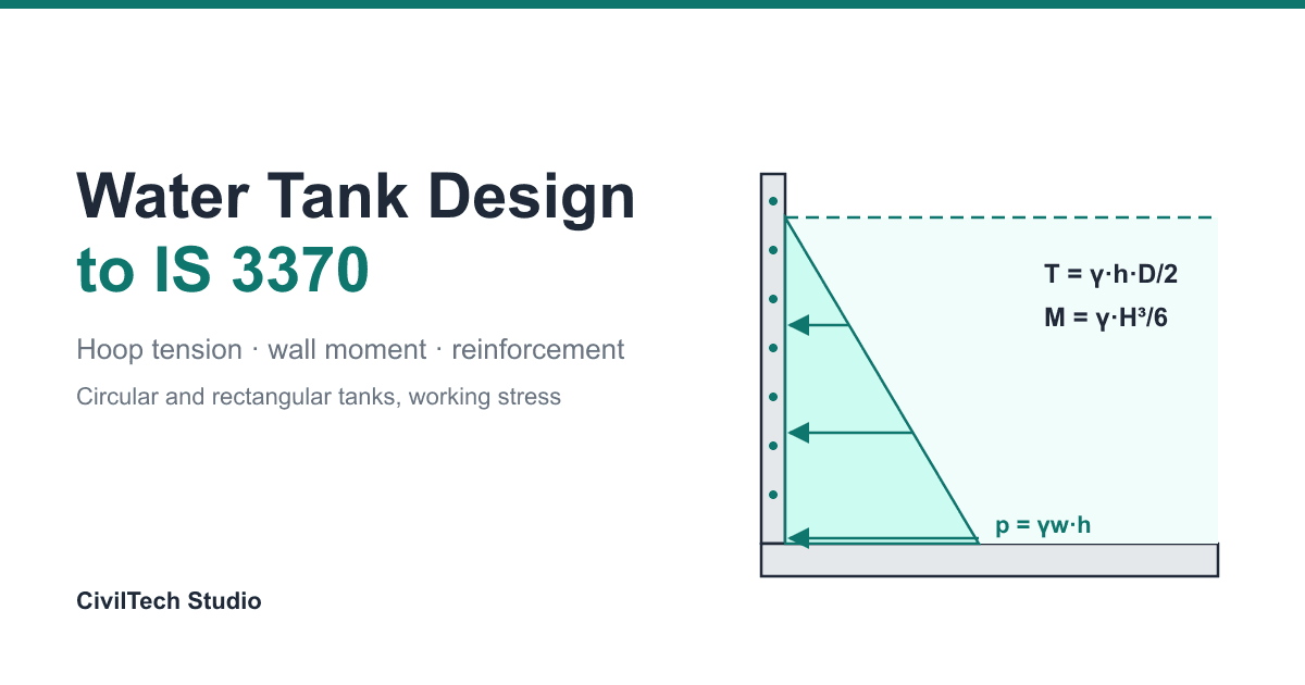
Water at depth h below the surface pushes on the wall with
p = γw × h γw = 9.81 kN/m³ for water
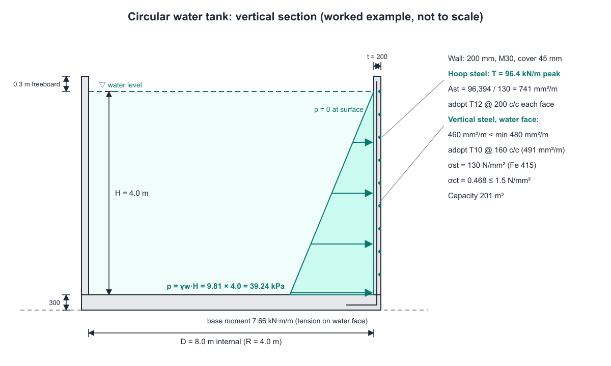
The pressure is zero at the water surface and largest at the base, so the load on the wall is a triangle. For 4 m of water, the base pressure is 9.81 × 4 = 39.24 kPa. Freeboard (the module defaults to 0.3 m) is not loaded, but it sets the wall height.
Circular water tank design: hoop tension and base moment
Membrane theory (wall free to slide at the base)
If the wall could slide freely on its base, each horizontal ring would carry the outward pressure as pure tension:
T = γw × h × D / 2 (kN per metre height)
At the base of an 8 m tank with 4 m of water: T = 9.81 × 4 × 8 / 2 = 156.96 kN/m. This is the familiar textbook formula, and it is correct only for a sliding base.
Real walls are restrained at the base
Most ground tanks are cast monolithic with the base slab, so the bottom of the wall cannot move outward. The base takes part of the load by cantilever action. This has two effects:
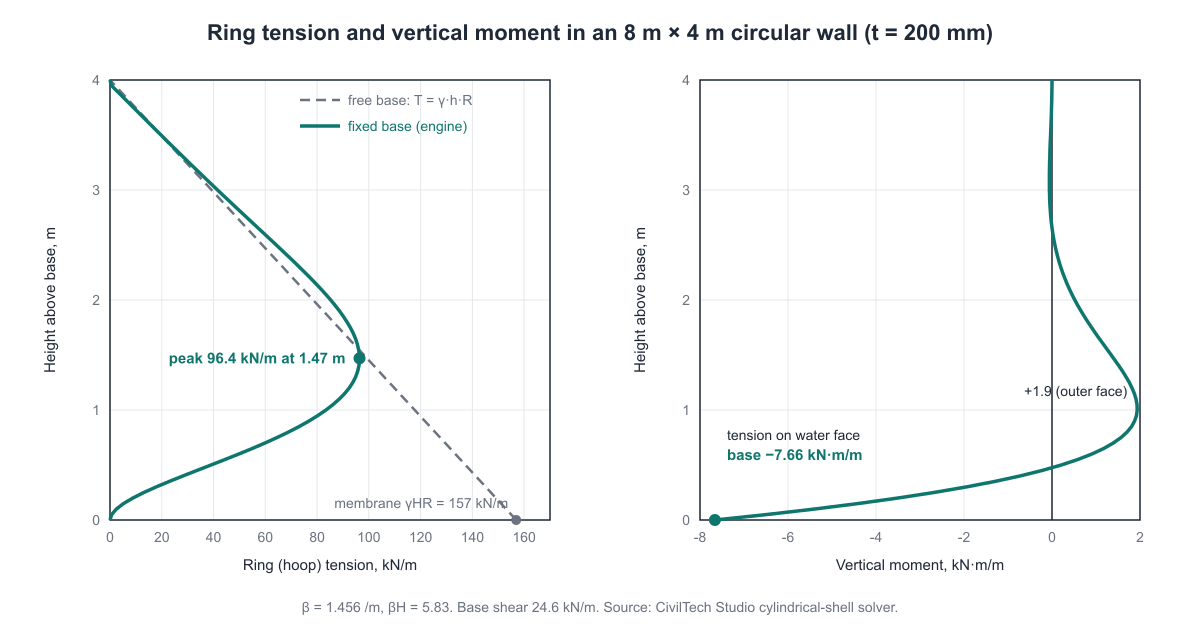
- The ring tension at the base drops to nearly zero, and the peak ring tension moves up the wall to roughly a third of the depth.
- A vertical bending moment appears at the base, with tension on the water face.
IS 3370 Part 4 tabulates coefficients for both effects against the parameter H²/(D·t). The CivilTech Studio engine solves the underlying cylindrical-shell equation directly, using the characteristic parameter
β = [ 3(1 − ν²) / (R² t²) ]^0.25 ν = 0.2 for concrete
For a long wall (βH greater than about 3), the closed-form results for a fixed base are:
Base moment      M0 = (1 − 1/(βH)) × γ R H t / √(12(1 − ν²))
Base shear       Q0 = γ R t / √(12(1 − ν²)) × (2βH − 1)
Ring tension     Nθ(x) = γ R [ (H − x) − e^(−βx) ( H cos βx + (H − 1/β) sin βx ) ]
Here x is the height above the base. These formulas are useful for hand-checking a computer result, as the worked example below does.
Rectangular water tank design: cantilever and panel action
A rectangular wall carries the water pressure by bending, not ring tension.
-
Cantilever wall (long walls, or walls with no effective support from the cross walls): the base moment is the triangular load ½γH² acting at H/3:
M = γ H³ / 6 -
Two-way panel (walls supported by adjacent walls and the base): moments in the vertical and horizontal directions come from the IS 3370 Part 4 panel coefficients, which depend on the panel's length-to-height ratio and edge conditions.
-
Direct pull: each wall is also pulled along its length by the reaction of the wall at right angles to it, T = γ × H × (span of the perpendicular wall)/2. The short wall carries the larger pull, because it holds the end reaction of the long wall.
The cube in the formula is what catches people out. Going from 3 m to 4 m of water raises the cantilever moment by (4/3)³ = 2.37 times.
Step-by-step: water tank design to IS 3370 (working stress)
- Fix the geometry. Capacity, liquid depth H, diameter D (or L × B), freeboard. A common starting wall thickness is 200 mm for small tanks.
- Choose materials. M30 minimum, Fe 415 or Fe 500, 45 mm cover on the liquid face.
- Compute the forces per metre run: hoop tension T and vertical moment M (circular), or M and direct pull (rectangular).
- Hoop / direct-tension steel: Ast = T / σst.
- Bending steel: Ast = M / (σst · j · d), with the working-stress lever arm
k = m σcbc / (m σcbc + σst) j = 1 − k/3 - Section adequacy: M must not exceed the balanced moment of resistance, M_bal = ½ σcbc k j b d². If it does, thicken the wall.
- No-crack check in direct tension: σct = T / (1000 t + (m − 1) Ast) must not exceed the permissible σct.
- Minimum steel: at least the IS 3370-2 cl. 8.1.1 percentage in each direction.
- Crack width, shear and durability checks.
- Base slab and stability: base moment from the wall, uplift and flotation if groundwater is present.
Worked example: 8 m diameter circular tank, 4 m water depth
These inputs are the module's defaults. The numbers below are the engine's output (see worked_example.py and worked_example.txt alongside this article).
Inputs
| Parameter | Value |
|---|---|
| Shape | Circular, ground-supported, wall fixed to base |
| Internal diameter D | 8.0 m (R = 4.0 m) |
| Liquid depth H | 4.0 m, freeboard 0.3 m |
| Wall thickness t | 200 mm |
| Concrete / steel | M30 / Fe 415 |
| Cover / bar | 45 mm / 12 mm |
| Base slab | 300 mm |
Engine results
| Result | Value |
|---|---|
| Capacity | 201.1 m³ |
| Shell parameter β | 1.456 /m (βH = 5.83) |
| Membrane hoop tension at base (for reference) | 156.96 kN/m |
| Peak hoop tension (fixed base) | 96.39 kN/m at 1.47 m above base |
| Base moment (tension on water face) | 7.66 kN·m/m |
| Base radial shear | 24.63 kN/m |
| Hoop steel required | 741 mm²/m |
| Vertical steel for bending | 460 mm²/m |
| Minimum steel (0.24 %, tank under 15 m) | 480 mm²/m |
| Balanced moment of resistance | 39.93 kN·m/m |
| Direct tensile stress in concrete | 0.468 N/mm² (limit 1.5) |
| Crack width, hoop direction | 0.207 mm at σst, 0.000 mm at the actual 85 N/mm² (limit 0.2) |
| Early-thermal crack width | 0.192 mm (limit 0.2) |
| Wall shear τv / τc | 0.165 / 0.253 N/mm² |
| Combined tension + bending ratio | 0.50 (limit 1.0) |
| Overall status | All checks pass |
Hand check of the key numbers
Capacity: π × 4² × 4 = 201.06 m³.
β: 3 × (1 − 0.2²) / (4² × 0.2²) = 2.88 / 0.64 = 4.5; 4.5^0.25 = 1.4565 /m. βH = 1.4565 × 4 = 5.826.
Base moment: √(12 × 0.96) = 3.394. γRHt = 9.81 × 4 × 4 × 0.2 = 31.39. M0 = (1 − 1/5.826) × 31.39 / 3.394 = 0.8284 × 9.249 = 7.66 kN·m/m. This matches the engine.
Base shear: γRt / 3.394 = 7.848 / 3.394 = 2.312; × (2 × 5.826 − 1) = 2.312 × 10.65 = 24.63 kN/m. This matches.
Peak ring tension at x = 1.47 m: βx = 2.141, e^(−2.141) = 0.1176, cos 2.141 = −0.540, sin 2.141 = 0.842, H − 1/β = 3.313. Nθ = 39.24 × [2.53 − 0.1176 × (4 × (−0.540) + 3.313 × 0.842)] = 39.24 × (2.53 − 0.074) = 96.4 kN/m. The closed form gives 96.37 kN/m against the engine's 96.39 kN/m. The small difference is because the closed form treats the wall as infinitely tall; the engine solves the finite wall.
Hoop steel: 96.39 × 1000 / 130 = 741 mm²/m. A 200 mm wall takes its ring steel in two layers (IS 3370-2:2009 cl. 8.1.1), so each face needs 741 / 2 = 371 mm²/m. That is T12 at 305 mm, but the bars may not be spaced wider than 200 mm, so the spacing limit governs. Adopt T12 @ 200 c/c each face (565 mm²/m per face, 1,131 mm²/m in all).
Crack width, hoop direction: with T12 at 200 mm and 45 mm cover, a_cr = √(100² + 51²) − 6 = 106 mm. At the full permissible stress (no tension stiffening), w = 3 × 106 × 130 / 200,000 = 0.207 mm, just over 0.2 mm. The provided steel is not stressed that high, though: σs = 96,390 / 1,131 = 85 N/mm², so ε1 = 85 / 200,000 = 4.3 × 10⁻⁴. The IS 3370-2 Annex B-6 stiffening term is ε2 = 2 × 1000 × 200 / (3 × 200,000 × 1,131) = 5.9 × 10⁻⁴. Because ε2 exceeds ε1, the mean strain is zero and the crack width at the actual stress is 0.000 mm. The module's verdict uses this actual-stress value, so the hoop crack check passes.
Lever arm: d = 200 − 45 − 6 = 149 mm. k = 9.333 × 10 / (93.33 + 130) = 0.418, j = 1 − 0.418/3 = 0.861.
Vertical steel: 7.66 × 10⁶ / (130 × 0.861 × 149) = 460 mm²/m, which is below the minimum of 0.0024 × 200 × 1000 = 480 mm²/m, so the minimum governs. Adopt T10 @ 160 c/c (491 mm²/m) on the water face, with the bars lapped into the base slab.
Section adequacy: M_bal = 0.5 × 10 × 0.418 × 0.861 × 1000 × 149² = 39.9 × 10⁶ N·mm = 39.9 kN·m/m, which is more than 7.66. The wall is adequate in bending.
No-crack check: 96,394 / (200,000 + 8.333 × 741) = 96,394 / 206,179 = 0.468 N/mm², which is below 1.5 N/mm².
The fixed base matters here. Designing this wall by membrane theory would call for 156.96 × 1000 / 130 = 1,207 mm²/m of hoop steel at the base, where the real ring tension is close to zero. It would also miss the base moment completely. Hoop tension falls off toward the top of the wall, so the hoop steel can be reduced in the upper third, provided the minimum steel is kept.
Contrast: a rectangular tank with the same depth
The module's rectangular default is 6 m × 4 m with 4 m of water and 200 mm cantilever walls:
M = 9.81 × 4³ / 6 = 104.64 kN·m/m
That is more than 13 times the circular tank's base moment, and well over the 39.93 kN·m/m balanced capacity of a 200 mm wall. The engine flags the wall as over-stressed and asks for at least 300 mm. You can test a thicker wall or two-way panel action in the rectangular water tank design tool. A circular plan is far more efficient for holding water because ring tension is resisted by the whole wall thickness.
IS 3370 vs ACI 350 vs Eurocode 2 for the same tank
The module can re-design the same forces to ACI 350 or EN 1992-3. Geometry, loads and shell analysis stay the same; only the steel design method and the crack criterion change.
| Code (method) | Load factor on water | Hoop steel | Vertical steel | Governing wall steel |
|---|---|---|---|---|
| IS 3370-2 (working stress, σst = 130 N/mm²) | 1.0 | 741 mm²/m | 460 mm²/m | 741 mm²/m |
| ACI 350-06 (strength, sanitary factor 1.65 tension / 1.30 flexure) | 1.4 | 596 mm²/m | 447 mm²/m | 596 mm²/m |
| EN 1992-3 / EC2 (limit state, fyd = fyk/1.15) | 1.2 | 321 mm²/m | 314 mm²/m | 480 mm²/m (minimum) |
ACI hoop steel: 1.65 × 1.4 × 96.39 × 1000 / (0.9 × 415) = 596 mm²/m. EC2 hoop steel: 1.2 × 96.39 × 1000 / 361 = 321 mm²/m.
The EC2 strength result is not the final answer. With T12 @ 200 on each face (the spacing limit governs again), the module checks the characteristic crack width to EN 1992-1-1 cl. 7.3.4. Each face's effective tension area is 100 mm deep (half the wall), so ρp,eff = 565 / (100 × 1000) = 0.00565. That gives s_r,max = 3.4 × 45 + 0.8 × 1.0 × 0.425 × 12 / 0.00565 = 875 mm. At σs = 85 N/mm², the strain term falls to its floor of 0.6 × 85 / 200,000 = 2.56 × 10⁻⁴. So w_k = 875 × 2.56 × 10⁻⁴ = 0.22 mm, against the 0.20 mm limit, and the EC2 design fails. The module asks for T12 @ 185 on each face (611 mm²/m per face), which brings w_k down to 0.19 mm. In a limit-state tank design, crack width usually governs, not strength.
IS clause reference for water tank design
| Topic | Code and clause | What it controls |
|---|---|---|
| Minimum grade | IS 3370-1:2009 Table 1 | M30 for RC (M25 for small tanks) |
| Exposure and cover | IS 3370-1 cl. 4 → IS 456 Table 16 | Severe exposure, 45 mm |
| Permissible steel stress | IS 3370-2:2009 Table 4 | 130 / 115 N/mm² |
| Concrete tension (no-crack) | IS 3370-2:2009 Table 1 | σct by grade |
| Minimum reinforcement | IS 3370-2:2009 cl. 8.1.1 | 0.35 % / 0.24 % HYSD |
| Crack width | IS 3370-2:2009 | 0.2 mm / 0.1 mm |
| Wall coefficients | IS 3370-4 | Ring tension, moments, panel coefficients |
| σcbc, modular ratio | IS 456 Table 21, Annex B | Working-stress section |
| Shear | IS 456 Table 23 | Permissible τc |
| Seismic (optional) | IS 1893-2:2014 | Impulsive and convective pressures |
Common mistakes in water tank design
- Using T = γHD/2 at the base of a monolithic wall. It overstates the base hoop steel and misses the base moment, which then cracks the water face at the wall–slab junction.
- Designing to IS 456 limit state without a crack check. A wall sized for strength only will leak.
- Forgetting the H³ in rectangular walls. Deep rectangular tanks need thick walls or buttresses; there is no cheap way around the cube.
- Ignoring direct pull in rectangular walls, which adds to the horizontal steel.
- Below-minimum steel. The 0.24 % / 0.35 % rule governs many small tanks, as it did for the vertical steel above.
- Checking only the full tank. An empty underground tank faces earth and groundwater pressure from outside, and can float. Check flotation with the tank empty.
- Using M20 or M25 for a tank larger than 50 m³. IS 3370-1 asks for M30.
How CivilTech Studio does this
The water tank design module runs the calculation shown above on a Python engine:
- Circular and rectangular tanks. Circular walls use a cylindrical-shell solver for fixed, hinged or free bases. Rectangular walls use cantilever action, a single coefficient, or the IS 3370 Part 4 two-way panel table, with per-wall direct pull.
- Working-stress checks: σst, balanced moment of resistance, concrete direct tension, combined tension plus bending, shear to IS 456 Table 23, minimum steel to IS 3370-2 cl. 8.1.1, minimum grade and cover.
- Crack control: crack width in the hoop and flexure directions, early-thermal and seasonal cracking, and temperature-and-shrinkage steel.
- Below-ground and stability checks: earth and groundwater pressure on the empty tank, uplift and flotation factor of safety, sliding, overturning, bearing and settlement.
- Optional extras: seismic forces to IS 1893-2, roof slab or dome, multiple compartments, wall openings, and sulphate and chemical durability.
- Other codes: ACI 350 and EC2 re-design of the same tank.
- Outputs: a bar bending schedule, BOQ, calculation report PDF, DXF and IFC export, a 3D view and an auto-size optimiser.
The underground case usually overlaps with basement walls. For those, see the basement design module. Check the soil under the slab with the bearing capacity calculator. For bar laps at the wall–base junction, use the development length calculator. For the concrete itself, the concrete mix design calculator has a water-retaining exposure class (maximum w/c 0.45).
FAQ
What is the minimum grade of concrete for a water tank as per IS 3370?
M30 for reinforced concrete liquid-retaining structures under IS 3370-1:2009 Table 1. M25 is allowed only for small tanks of 50 m³ or less where M30 is impracticable, and not in coastal areas.
How do you calculate hoop tension in a circular water tank?
For a wall free to slide at its base, T = γ × H × D / 2 per metre height, which is largest at the base. For a wall fixed to its base, the peak is lower and occurs higher up the wall. Use IS 3370 Part 4 coefficients or a shell analysis. In the 8 m × 4 m example, the peak is 96.4 kN/m against a membrane value of 157 kN/m.
What is the permissible stress in steel for a water tank?
Under the working-stress method of IS 3370-2:2009, 130 N/mm² for high-yield deformed bars (Fe 415/Fe 500) and 115 N/mm² for mild steel. The low value is what keeps cracks narrow.
What is the minimum reinforcement in a water tank wall?
IS 3370-2:2009 cl. 8.1.1 asks for 0.35 % of the surface-zone concrete in each direction for HYSD bars. This reduces to 0.24 % when no dimension of the tank exceeds 15 m. For a 200 mm wall in a small tank, that is 480 mm²/m in each direction.
What wall thickness should a water tank have?
There is no single answer. Start at about 200 mm for small circular tanks, then confirm that the section's balanced moment and the concrete direct-tension stress are within limits. Rectangular walls usually need more: the 4 m deep cantilever example needs at least 300 mm.
Is IS 3370 limit state or working stress?
IS 3370-2:2009 allows both: limit-state design with a crack-width check, or the working-stress method, in which the low steel stress serves as the crack control. This calculator uses working stress for IS 3370 and limit state for the ACI 350 and EC2 options.
How do you check an underground water tank for uplift?
Take the tank empty, with the groundwater at its highest level. Compare the weight of the slab, walls and any soil on the base projection with the buoyant uplift. A factor of safety of 1.2 is the module's default target.
Educational reference. Always verify against the governing code and your project specification.