#masonry-design#is-1905#load-bearing-wall#brick-masonry#is-4326#seismic-detailing
Masonry Wall Design (IS 1905) — Worked Example
Masonry wall design to IS 1905 step by step: slenderness ratio, basic stress fb, stress reduction factor ks, ka, kp, permissible vs actual stress, eccentricity, and IS 4326 seismic bands, with a fully checked 230 mm G+2 brick wall example.
Updated 4 Nov 202617 min read
 Try it free: run this design in Masonry Wall DesignOpen →
On this page
- What governs a load-bearing masonry wall under IS 1905
- Step-by-step procedure for load-bearing wall design
- Worked example: brick wall design calculation for a G+2 house
- IS 1905 clause reference
- IS 1905 compared with Eurocode 6 and TMS 402
- Common mistakes in masonry wall design
- How CivilTech Studio does this
- FAQ
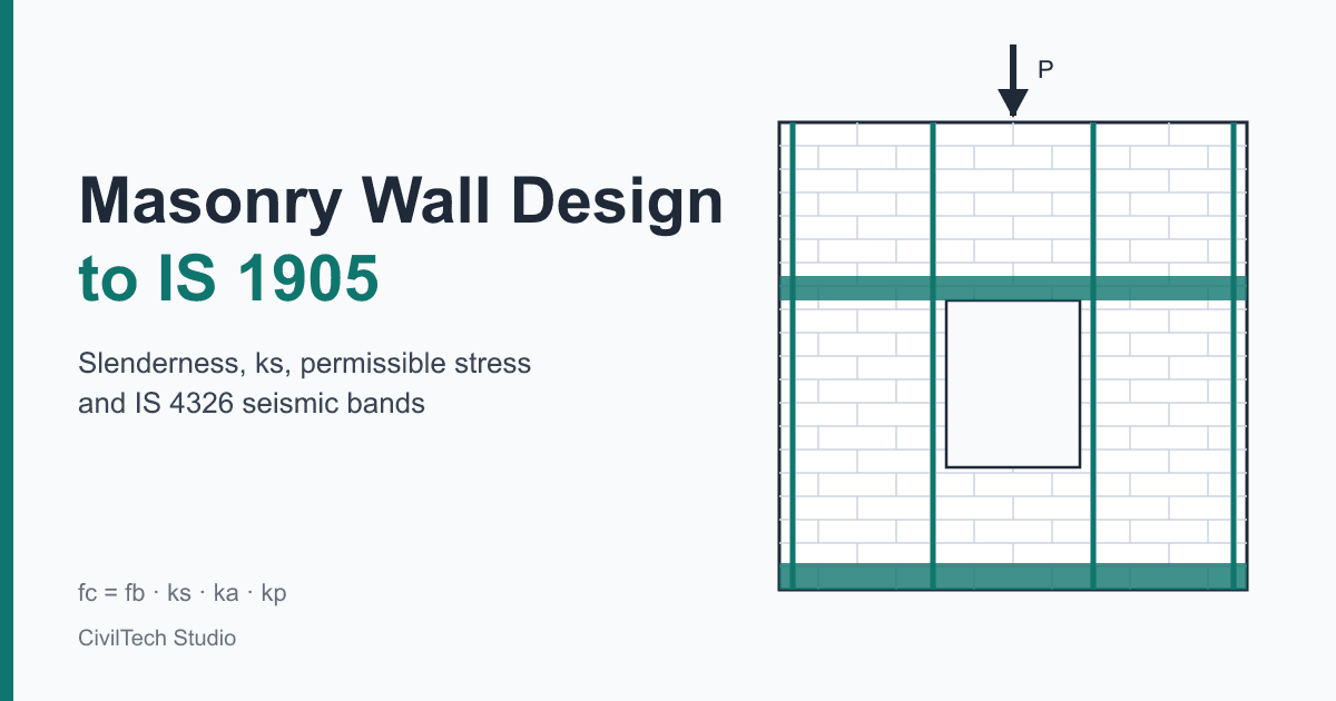
Masonry wall design to IS 1905 is a working-stress check. You work out the actual compressive stress in the wall, fa = P / (t · L), and compare it with the permissible stress fc = fb · ks · ka · kp. Here fb is the basic stress for your brick and mortar (Table 8), ks reduces it for slenderness and eccentricity (Table 9), ka reduces it for small cross-sections and kp adjusts it for unit shape. The wall is adequate when fa ≤ fc, the slenderness ratio stays within 27, and, in seismic zones, the IS 4326 bands and vertical steel are provided. This guide goes through each step and then checks a real 230 mm ground-floor wall of a G+2 house in Patna (Zone IV), number by number.
By the CivilTech Studio Engineering Team
What governs a load-bearing masonry wall under IS 1905
Five things decide whether an unreinforced brick wall carries its load:
- Slenderness ratio (SR). This is the effective height divided by the effective thickness, or the effective length divided by the effective thickness, whichever is less (IS 1905 Cl. 4.6.1). The effective height comes from Table 4, the effective length from Table 5. For a solid wall the effective thickness is the actual thickness. Load-bearing walls in cement or cement-lime mortar are limited to SR = 27.
- Eccentricity of the vertical load (e/t). Slab reactions rarely act on the wall centreline. The eccentricity ratio feeds Table 9. Above e/t = 1/24 it also changes how the stress is checked (Cl. 5.4.1.4).
- Basic compressive stress fb (Table 8). This depends on the crushing strength of the brick and the mortar grade.
- Modification factors.
ka = 0.7 + 1.5Afor a cross-section smaller than 0.2 m² (A in m², Cl. 5.4.1.2).kpfrom Table 10 rewards tall units (height-to-width ratio above 0.75) of strength up to 15 N/mm². - Seismic detailing. IS 4326 and IS 13828 require RC bands and vertical bars at corners and jambs. The requirement depends on the seismic zone and the number of storeys.
Mortar grades in IS 1905
Site engineers often get this wrong. IS 1905 names mortars by grade, not by mix:
| Grade | Cement : sand | Cement : lime : sand (alternative) |
|---|---|---|
| H1 | 1 : 3 | 1 : ¼ : 3 |
| H2 | 1 : 4 | 1 : ½ : 4½ |
| M1 | 1 : 5 | 1 : 1 : 6 |
| M2 | 1 : 6 | 1 : 2 : 9 |
| M3 | 1 : 7 | 1 : 3 : 12 |
The common site mix of 1:6 cement mortar is M2, not M1. That choice alone changes fb for a 7.5 MPa brick from 0.74 to 0.59 N/mm².
Step-by-step procedure for load-bearing wall design
1. Load per metre run       P (kN/m) = slab reactions + walls above + parapet + finishes
2. Effective height         he = k × H        (IS 1905 Table 4)
3. Slenderness ratio        SR = he / t       (≤ 27; use le / t if cross walls are close)
4. Eccentricity ratio       e/t,  e = Σ(Pi · ei) / ΣPi
5. Basic stress             fb from Table 8 (brick strength, mortar grade)
6. Stress reduction factor  ks from Table 9 (SR, e/t), interpolated both ways
7. Area and shape factors   ka = 0.7 + 1.5A if A < 0.2 m², else 1.0;  kp from Table 10
8. Permissible stress       fc = fb · ks · ka · kp
9. Actual stress            fa = P / (t · L)      (N and mm give N/mm²)
10. Check                   e/t ≤ 1/24         : fa ≤ fc
                            1/24 < e/t ≤ 1/6   : fa(1 + 6e/t) ≤ 1.25 fc
                            1/6 < e/t ≤ 1/3    : 2P / [3L(t/2 − e)] ≤ 1.25 fc  (cracked section)
11. Seismic bands and vertical steel to IS 4326 / IS 13828
Effective-height factors used for Table 4:
| End condition | he |
|---|---|
| Both ends restrained (RC slabs bearing on the wall top and bottom) | 0.75 H |
| One end restrained, the other partially restrained | 0.85 H |
| Both ends laterally supported only | 1.00 H |
| Free top (parapet, compound wall, cantilever) | 1.50 H |
Excerpt of Table 8, basic compressive stress fb (N/mm²):
| Brick strength (MPa) | H1 | H2 | M1 | M2 | M3 |
|---|---|---|---|---|---|
| 3.5 | 0.35 | 0.35 | 0.35 | 0.35 | 0.25 |
| 5.0 | 0.50 | 0.50 | 0.50 | 0.44 | 0.41 |
| 7.5 | 0.75 | 0.74 | 0.74 | 0.59 | 0.56 |
| 10.0 | 1.00 | 0.96 | 0.96 | 0.81 | 0.75 |
| 12.5 | 1.16 | 1.09 | 1.06 | 0.94 | 0.87 |
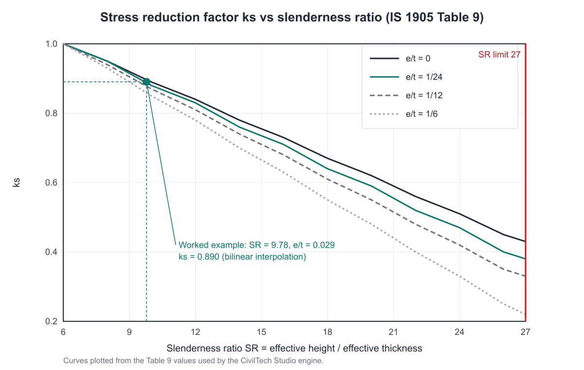
Excerpt of Table 9, stress reduction factor ks:
| SR | e/t = 0 | 1/24 | 1/12 | 1/6 |
|---|---|---|---|---|
| 6 | 1.00 | 1.00 | 1.00 | 1.00 |
| 8 | 0.95 | 0.95 | 0.94 | 0.93 |
| 10 | 0.89 | 0.88 | 0.87 | 0.85 |
| 12 | 0.84 | 0.83 | 0.81 | 0.78 |
| 16 | 0.73 | 0.71 | 0.68 | 0.63 |
| 20 | 0.62 | 0.59 | 0.55 | 0.48 |
Worked example: brick wall design calculation for a G+2 house
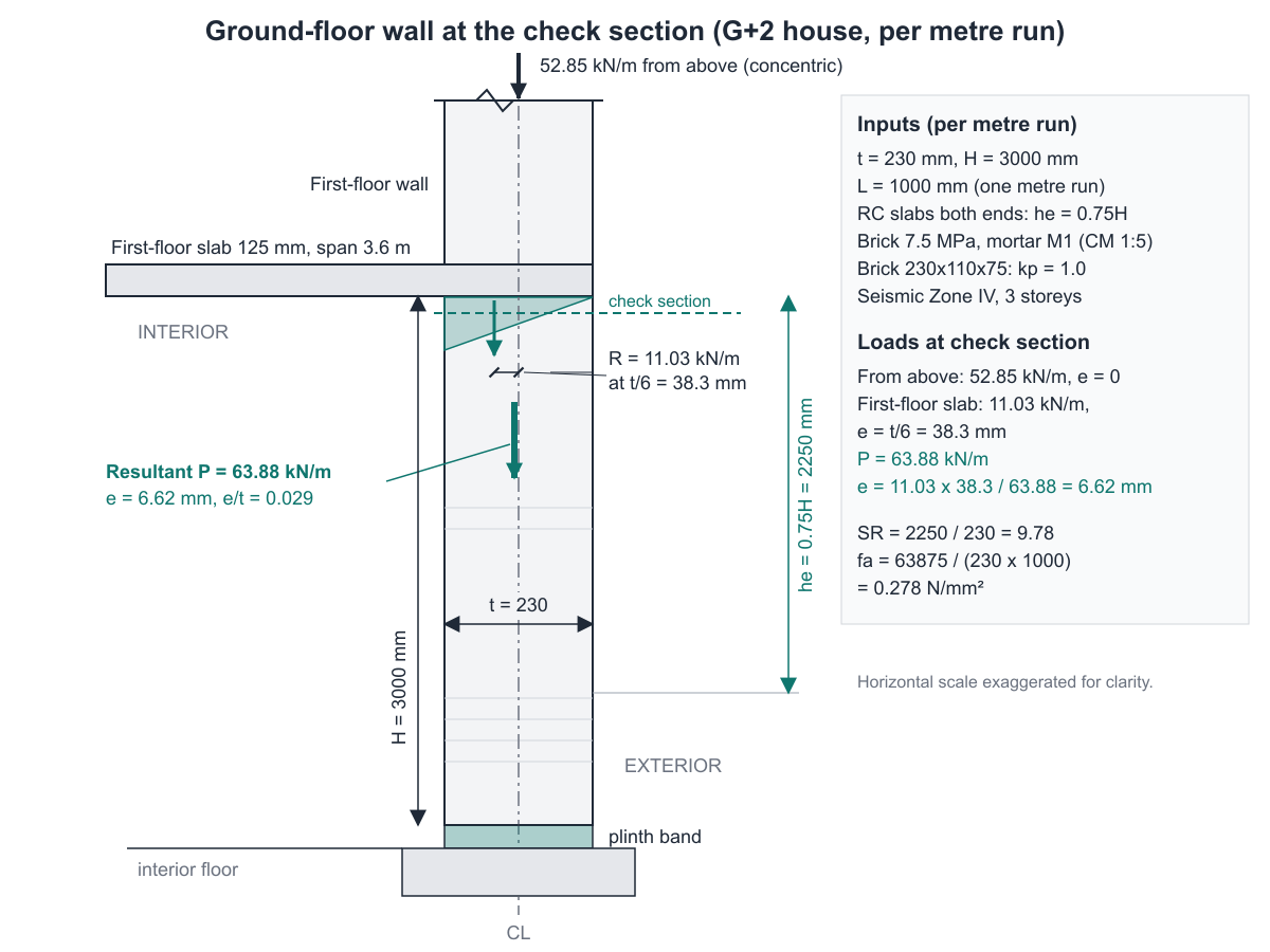
Problem. A 230 mm external brick wall on the ground floor of a G+2 house in Patna (Seismic Zone IV). The clear storey height is 3.0 m. RC slabs 125 mm thick span 3.6 m onto the wall at every level. Bricks are 7.5 MPa, 230 × 110 × 75 mm, laid in M1 mortar (CM 1:5). Design one metre run (L = 1000 mm).
Load build-up per metre run
Unit weights: RCC 25 kN/m³, plastered brickwork 20 kN/m³. Roof: 3.125 slab + 2.0 brick-bat coba and finishes + 1.5 live load = 6.625 kN/m². Floors: 3.125 slab + 1.0 finish + 2.0 live load = 6.125 kN/m². Each slab reaction is w × 3.6 / 2. Openings are ignored, which is conservative.
| Load (section just below first-floor slab) | kN/m | Eccentricity |
|---|---|---|
| Parapet, 115 mm × 1.0 m | 2.300 | 0 |
| Roof slab reaction, 6.625 × 1.8 | 11.925 | 0 |
| Second-floor wall, 0.23 × 3.0 × 20 | 13.800 | 0 |
| Second-floor slab reaction, 6.125 × 1.8 | 11.025 | 0 |
| First-floor wall | 13.800 | 0 |
| First-floor slab reaction (bears on this wall) | 11.025 | t/6 = 38.3 mm |
| Total P | 63.875 |
The first-floor slab bears on the full wall width. Assume a triangular bearing pressure: its reaction then acts t/3 from the inner face, which is t/6 = 38.3 mm from the centreline. The loads from above are taken as concentric at this level. Resultant eccentricity:
e   = 11.025 × 38.33 / 63.875 = 6.62 mm
e/t = 6.62 / 230 = 0.0288   (< 1/24 = 0.0417, so bending is ignored)
Hand calculation
Effective height   he = 0.75 × 3000 = 2250 mm
Slenderness ratio  SR = 2250 / 230 = 9.78          < 27  OK
Basic stress       fb = 0.74 N/mm²                 (Table 8: 7.5 MPa, M1, tabulated)
ks, row SR 8       0.95 at e/t 0 and 1/24  → 0.950
ks, row SR 10      0.89 − (0.89 − 0.88) × 0.0288/0.0417 = 0.8831
ks at SR 9.78      0.950 − (0.950 − 0.8831) × (9.78 − 8)/2 = 0.8904
Area factor        A = 0.23 × 1.0 = 0.23 m² ≥ 0.2  → ka = 1.0
Shape factor       H/W = 75/110 = 0.68 ≤ 0.75      → kp = 1.0
Permissible        fc = 0.74 × 0.8904 × 1.0 × 1.0 = 0.659 N/mm²
Actual             fa = 63 875 / (230 × 1000)    = 0.278 N/mm²
Utilisation        0.278 / 0.659 = 0.42           SAFE
At the foot of the same wall, the ground-floor wall adds its own 13.8 kN/m, giving P = 77.675 kN/m. The slab eccentricity has dissipated there (e = 0), so ks = 0.950 − 0.06 × 0.891 = 0.8965, fc = 0.663 N/mm², fa = 0.338 N/mm² and the utilisation is 0.51. The base governs on stress and the top section governs on eccentricity. Check both.
Engine results versus the hand check
We ran the same inputs through the CivilTech Studio engine, with the argument mapping the masonry wall design calculator uses:
| Quantity | Engine | Hand |
|---|---|---|
| Effective height he | 2250 mm | 2250 mm |
| Slenderness ratio SR (height governs) | 9.78 | 9.78 |
| Eccentricity ratio e/t | 0.029 | 0.0288 |
| Basic stress fb | 0.740 N/mm² | 0.74 |
| Stress reduction factor ks | 0.890 | 0.8904 |
| ka / kp | 1.000 / 1.00 | 1.0 / 1.0 |
| Permissible stress fc | 0.659 N/mm² | 0.659 |
| Actual stress fa | 0.278 N/mm² | 0.278 |
| Utilisation, top section | 0.42 | 0.42 |
| Utilisation, base section (P = 77.675, e = 0) | 0.51 | 0.51 |
Every value agrees. The engine also reports a length-based ratio, SR_l = 3.48, but does not credit it because no cross-wall spacing was entered. That is correct: on a per-metre design the 1000 mm loaded length is not the distance between cross walls.
What changes with brick and mortar grade
Same load and eccentricity, engine runs:
| Brick, mortar | fb | fc | fa | Utilisation |
|---|---|---|---|---|
| 7.5 MPa, M1 (CM 1:5), base case | 0.74 | 0.659 | 0.278 | 0.42 |
| 7.5 MPa, M2 (CM 1:6) | 0.59 | 0.525 | 0.278 | 0.53 |
| 3.5 MPa, M2 (CM 1:6) | 0.35 | 0.312 | 0.278 | 0.89 |
| 10 MPa, H2 (CM 1:4) | 0.96 | 0.855 | 0.278 | 0.32 |
Weak country bricks in 1:6 mortar use almost the whole capacity at the top of the ground-floor wall. At the base the same wall would be overstressed: fa = 0.338 against fc = 0.35 × 0.8965 = 0.314 N/mm². Brick strength is the input most worth testing before you commit to load-bearing construction. You can try your own brick and mortar grades in the load-bearing wall design tool.
IS 4326 seismic bands and vertical steel
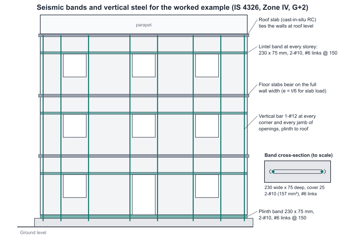
For Zone IV and three storeys the engine marks plinth, lintel and roof bands as mandatory, with vertical steel at all corners and at the jambs of openings:
| Item | Engine output |
|---|---|
| Plinth, lintel and roof bands | 230 × 75 mm RC, 2-#10 (Ast = 157 mm²), #6 links @ 150 mm c/c |
| Band depth rule | 75 mm with 2 bars (150 mm when 4 bars are used) |
| Vertical steel | 1-#12 (113 mm²) at every corner and every jamb, anchored into plinth and bands |
| Overall verdict | SAFE (axial OK, SR ≤ 27, e/t ≤ 1/3, detailing provided) |
Two points of interpretation:
- The engine maps band steel and bar size to zone and storey count. IS 4326 sets band steel by building category and wall span, so long walls between cross walls may need more than 2-#10. Read the schedule as a starting point for spans of ordinary rooms and check longer walls against the code tables.
- A cast-in-situ RC roof slab bearing on the wall ties the walls together at roof level. The separate roof band in IS 4326 matters most for trussed or joist-and-plank roofs.
Secondary check: the top-storey wall
The second-floor wall carries only the parapet and roof slab: P = 14.225 kN/m. The roof reaction is eccentric, so e = 11.925 × 38.33 / 14.225 = 32.14 mm and e/t = 0.140. That lies between 1/24 and 1/6, so the engine switches to the eccentric check:
ks (SR 9.78, e/t 0.140) = 0.865        fc = 0.74 × 0.865 = 0.640 N/mm²
fa   = 14 225 / 230 000 = 0.0618 N/mm²
fmax = 0.0618 × (1 + 6 × 0.140) = 0.114 N/mm²   vs 1.25 fc = 0.800   → utilisation 0.14
Compression is not a concern here. We also applied 1.0 kN/m² of face pressure, the order of design wind pressure for Patna (calculate yours with the wind pressure calculator). The engine treats the wall as spanning vertically and simply supported:
M = 1.0 × 3.0² / 8 = 1.125 kN·m/m      Z = 1000 × 230² / 6 = 8.82 × 10⁶ mm³/m
fbend = 1.125 × 10⁶ / 8.82 × 10⁶ = 0.128 N/mm²
permissible flexural tension (M1) = 0.07 × 4/3 = 0.093 N/mm²   → fails
This is a deliberately conservative model. It ignores two-way spanning between cross walls, and it does not subtract the precompression (0.062 N/mm² at the top), which would leave a net tension of about 0.066 N/mm². Still, the result is a fair warning: lightly loaded top-storey walls and parapets are where out-of-plane failure starts in earthquakes and storms. Keep cross walls close, tie the walls into the bands, or use a thicker wall where the geometry is unfavourable.
IS 1905 clause reference
| Item | Clause / table | Used for |
|---|---|---|
| Slenderness ratio, lesser of height and length based | Cl. 4.6.1 | SR |
| Effective height of walls | Table 4 | he = 0.75 / 0.85 / 1.0 / 1.5 H |
| Effective length of walls | Table 5 | le from cross-wall spacing |
| Basic compressive stress | Table 8 | fb |
| Stress reduction factor | Table 9 | ks (SR, e/t) |
| Area reduction factor | Cl. 5.4.1.2 | ka = 0.7 + 1.5A, A < 0.2 m² |
| Shape modification factor | Cl. 5.4.1.3, Table 10 | kp |
| Eccentric loads, 25 % stress increase | Cl. 5.4.1.4 | 1/24 < e/t ≤ 1/3 |
| Permissible flexural tension | Cl. 5.4.2 | 0.07 / 0.05 / 0.025 N/mm² (M1+ / M2 / M3) |
| Permissible shear stress | IS 1905 shear provisions | fs = 0.1 + fd/6 ≤ 0.5 N/mm², fd from dead load |
| Bands and vertical steel | IS 4326, IS 13828 | Seismic detailing |
IS 1905 compared with Eurocode 6 and TMS 402
| IS 1905:1987 | EN 1996-1-1 (Eurocode 6) | TMS 402 (ASD) | |
|---|---|---|---|
| Method | Working stress | Limit state | Allowable stress |
| Material input | fb from brick strength and mortar grade | fk, characteristic strength | f'm, specified strength |
| Capacity | fc = fb · ks · ka · kp | NRd = Φ · fd · A, fd = fk / γM | Fa = 0.25 f'm [1 − (h/140r)²] |
| Slenderness and eccentricity | ks from Table 9 | Φ = min(1 − 2ei/t, Annex G Φm) | h/r, minimum e = 0.1t, unity check |
| Load | Service load | Factored, e.g. 1.35G + 1.5Q | Service load |
For the same ground-floor wall, the engine's EC6 path gives the following. The inputs are G = 53.975 and Q = 9.9 kN/m, so NEd = 87.72 kN/m, with fk = 3.26 MPa (K = 0.55, normalised brick strength 6.4 MPa, mortar 5 MPa) and γM = 2.5:
fd = 3.26 / 2.5 = 1.304 N/mm²    Φ = 0.840    NRd = 0.840 × 1.304 × 230 000 = 252 kN/m
NEd / NRd = 87.72 / 252 = 0.35
That is broadly in line with the IS 1905 utilisation of 0.42 at the same section. One caution about the module's code switch: it re-runs the same inputs, and the strength it passes to TMS 402 or EC6 is the IS basic stress fb, a permissible value, not f'm or fk. The EC6 path also treats the entered load as the design load. The comparison is therefore very conservative unless you supply a true strength and a factored load. Use it as a sanity check, not as a design to those codes.
Common mistakes in masonry wall design
- Calling 1:6 cement mortar M1. It is M2. For 7.5 MPa bricks fb drops from 0.74 to 0.59 N/mm².
- Checking only the top or only the base. Eccentricity peaks under the slab and axial load peaks at the foot. In the example the base governed on stress (0.51 against 0.42).
- Using the full storey height as the effective height when slabs restrain both ends. This understates capacity. The opposite error, using 0.75H for a parapet or a wall with a free top, is unsafe: that case needs 1.5H.
- Crediting the length-based SR without real cross walls. Cl. 4.6.1 lets the lesser ratio govern only when cross walls or piers actually brace the wall at the spacing you use.
- Ignoring ka for piers and short walls. A 230 × 600 mm pier has A = 0.138 m², so ka = 0.7 + 1.5 × 0.138 = 0.907, a 9 % cut.
- Assuming the brick strength. Local bricks often test at 3.5 to 5 MPa. The sensitivity table shows what that does.
- Treating seismic bands as optional extras. In Zones III to V they are part of the design, not decoration.
How CivilTech Studio does this
The IS 1905 masonry wall design module runs the same engine used in this article.
Inputs. Axial load in kN on the wall length (enter kN/m with L = 1000 mm for a per-metre design; the app converts to N), storey height, thickness and length. End condition (the four Table 4 cases) and eccentricity. Optional cross-wall or pier spacing, which credits the length-based slenderness ratio. Brick strength and mortar grade (H1, H2, M1, M2, M3), plus optional unit height and width for kp. Seismic zone II to V and number of storeys. Optional in-plane storey shear with its dead-load share, opening width, soft-soil toggle, and lateral face pressure for the out-of-plane check.
Checks and outputs. Effective height and thickness, SR about height and length, e/t, fb, ks, ka, kp, fc, fa and utilisation. Extreme-fibre stress with the 1.25 increase when e/t exceeds 1/24, and a cracked-section check beyond 1/6. The SR ≤ 27 and e/t ≤ 1/3 limits. In-plane shear with fs = 0.1 + fd/6 ≤ 0.5 N/mm². Out-of-plane flexure. The verdict is an honest overall one: it fails the wall if any active check fails, or if mandatory seismic detailing is missing.
Detailing. Required plinth, lintel and roof bands and corner/jamb vertical steel, with a schedule tab listing band sections and bars.
Transparency and export. A calculation panel shows every formula with its clause reference. A chart plots permissible stress against slenderness with your wall marked. You also get a live parametric schematic, three ready-made presets, an IS 1905 / TMS 402 / Eurocode 6 compare drawer (read the caution above), and PDF and Excel reports in metric or imperial units.
For the foundation under the wall, continue in foundation design. For the lateral loads that feed the shear check, use the seismic base shear calculator and load combinations.
FAQ
What is the permissible compressive stress of brick masonry as per IS 1905? It is fc = fb · ks · ka · kp. For 7.5 MPa bricks in M1 mortar, fb = 0.74 N/mm². A 230 mm wall with a 3.0 m restrained storey has ks ≈ 0.89, so fc ≈ 0.66 N/mm².
What is the maximum slenderness ratio for a load-bearing brick wall? 27 for walls in cement or cement-lime mortar. SR is the effective height (or effective length) divided by the effective thickness. A 230 mm wall with a 3.0 m storey restrained by RC slabs has SR = 2250 / 230 = 9.78.
How do you find the stress reduction factor ks in IS 1905? Read Table 9 with the slenderness ratio and the eccentricity ratio e/t, and interpolate linearly in both directions. For SR 9.78 and e/t 0.029, ks = 0.890.
Which IS 1905 mortar grade is 1:6 cement mortar? M2. Cement-sand 1:5 (or cement-lime-sand 1:1:6) is M1, and 1:4 is H2.
Can a 230 mm brick wall carry a G+2 building? In the worked example it can: with 7.5 MPa bricks and M1 mortar the ground-floor wall reaches a utilisation of 0.51 at its base. With 3.5 MPa bricks in 1:6 mortar it would be overstressed at the base. Check your actual spans, brick strength and openings, and follow IS 4326 detailing.
When does eccentricity matter in a masonry wall? Up to e/t = 1/24 only ks changes. Between 1/24 and 1/6 you check the extreme-fibre stress fa(1 + 6e/t) against 1.25 fc. Beyond 1/6 the tension zone is ignored. The engine rejects e/t above 1/3.
Which seismic bands are required in Zone III and Zone IV? Under the module's IS 4326 rules, Zone III needs plinth, lintel and roof bands, with vertical steel for three storeys or more. Zones IV and V need all bands plus vertical bars at every corner and jamb.
When is the area reduction factor ka applied? When the horizontal cross-section is smaller than 0.2 m², as in piers and short wall segments: ka = 0.7 + 1.5A. A metre run of 230 mm wall (0.23 m²) takes ka = 1.0.
Educational reference. Always verify against the governing code and your project specification.